Continue to Site

Welcome to EDAboard.com

Welcome to our site! EDAboard.com is an international Electronics Discussion Forum focused on EDA software, circuits, schematics, books, theory, papers, asic, pld, 8051, DSP, Network, RF, Analog Design, PCB, Service Manuals... and a whole lot more! To participate you need to register. Registration is free. Click here to register now.

Altium - Connect bus to component pin

Status
Not open for further replies.

pcb2011

Newbie level 3
Joined
Mar 22, 2011
Messages
3
Helped
0
Reputation
0
Reaction score
0
Trophy points
1,281
Activity points
1,302
Hello,

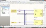
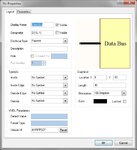
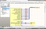
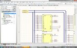
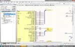
I created a component with a pin that has designator name D[16..1]. Its footprint includes 16 pins wtih names D1, D2, D3 up to D16. When I wire a bus to the pin on this component, connections are not made to the individual pins.

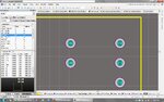
Hopefully the attached pictures better illustrate the problem. Basically, I want to wire a bus to a schematic component pin, and have each signal in the bus be connected to its approporiate PCB component pin.

Struggling with this one! Thanks for any tips.
 

Attachments

  • sch sheet 2 - use bus.jpg
    sch sheet 2 - use bus.jpg
    269.1 KB · Views: 201
  • component pin.jpg
    component pin.jpg
    79.9 KB · Views: 163
  • sch sheet 1 - create bus.jpg
    sch sheet 1 - create bus.jpg
    339.4 KB · Views: 232
  • corner of footprint.jpg
    corner of footprint.jpg
    246.7 KB · Views: 146
Last edited:

I haven't used bus pins for components. If that could even possibly be it, a debugging step would be to break it out into normal pins.

In-re pic #3: I think that the wire label and the bus label must match each other exactly (except for the index number at the end). But don't NEED to match the port name, particularly in a hierarchical design. Try naming the wires D1, D2, .... and not DSC_D1 ....
 
I'm not aware of a way to place a bus directly on a component (you would normally break the bus out to the individual pins), but I think you can accomplish what you want with a Device Sheet:

**broken link removed**
 
Thanks for your help guys,

I took the advice and broke out the bus to pins. I am almost there, but I don't get connections between sheets unless I have scope set to global. I am trying to use flat scope. Attached is my shematics. What am I missing (naming conventions??). I have tried many different port names, with and withot the [#..#] aferwards. I can't get the port to connect the bus to another sheet.

Thank in advance!
 

Attachments

  • sch1.jpg
    sch1.jpg
    322.8 KB · Views: 146
  • sch2.jpg
    sch2.jpg
    344 KB · Views: 154

I'd suggest you put a Net Label on each Bus (Place -> Net Label), i.e. D[1..16] and EN[1..5]. On your Ports use the same names (D[1..16], not DSC D[16..1]). That should be all you need to do, otherwise your schematic looks OK. I'd leave scope set to Automatic - if you want a signal to connect to another sheet you should define a port to show it goes off-sheet (Global means any net label will connect to a net label of the same name on any other sheet). If your nets aren't connecting there is some kind of problem with your Ports. Ports are how you should tell Altium a net goes off-sheet, but the port name has to match the net name.

Thanks for your help guys,

I took the advice and broke out the bus to pins. I am almost there, but I don't get connections between sheets unless I have scope set to global. I am trying to use flat scope. Attached is my shematics. What am I missing (naming conventions??). I have tried many different port names, with and withot the [#..#] aferwards. I can't get the port to connect the bus to another sheet.

Thank in advance!
 
Thanks a lot Kevin54, you are an Altium genius! I was missing the matching net labels on the bus. Amateur mistake :)
 

Status
Not open for further replies.

Part and Inventory Search

Welcome to EDABoard.com

Sponsor

Back
Top