Continue to Site

Welcome to EDAboard.com

Welcome to our site! EDAboard.com is an international Electronics Discussion Forum focused on EDA software, circuits, schematics, books, theory, papers, asic, pld, 8051, DSP, Network, RF, Analog Design, PCB, Service Manuals... and a whole lot more! To participate you need to register. Registration is free. Click here to register now.

Audio amplifier with bjt, but why caps between base/emitter and collector emitters?

Status
Not open for further replies.

spid3rx

Member level 2
Joined
Apr 26, 2010
Messages
44
Helped
6
Reputation
12
Reaction score
6
Trophy points
1,288
Activity points
1,644
Hi,

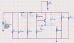
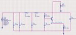
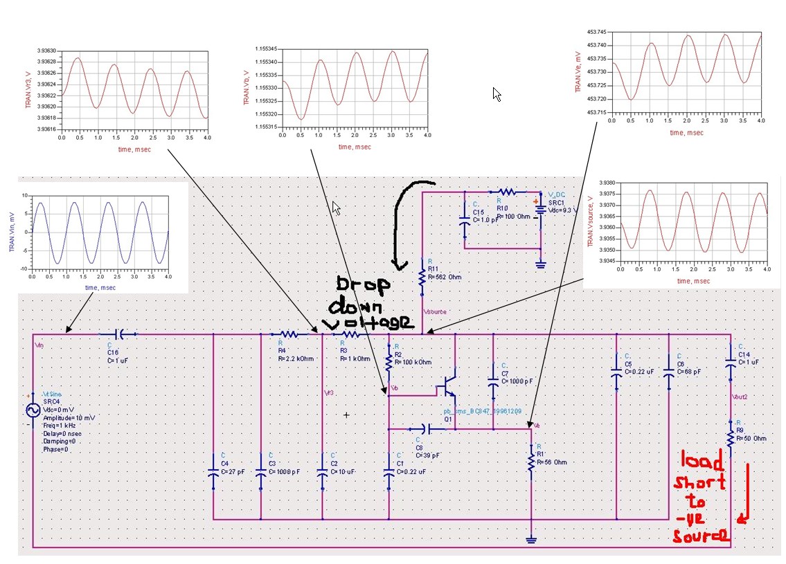
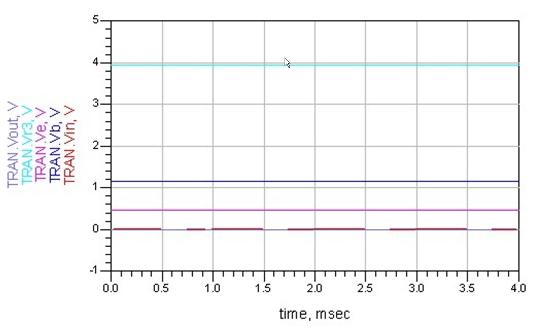
I come across a schematic on the microphone line, with a bjt which I believe is for audio signal amplification. I believe it is a common emitter type with Re=56 ohm. The thing is I don't understand why there is a capacitor with 39pF in between base and emitter, and another one 1000pF cap between collector and emitter? Anyone can explain the usage ?
39 pF with the 56ohm on emitter line as high pass filter ?
no idea on 1000pf ?
please help anyone knows. million thanks !
 

It would be helpful to have a circuit diagram. I suspect that the capacitors are there to stop radio frequencies being picked up. Taking the 39 Pf cap first, if there is no series impedance in the feed to it, then a high proportion of the Vin will appear at the emitter of the transistor, 80 ->99%. this is in phase with the voltage on the base so the current through the 39 Pf will only be 20 -> 1% of that expected (more or less the same voltage at both ends of it), so it will actually act like a capacitor 20 -> 1% of its face value( 6.8 -> .39 Pf), so I would not expect it to have much effect at all. Can't make any sense of the 1000 Pf C->E, C-> earth reduces the out put at high frequencies, E-> - 20 X E (what you would expect at the collector) would increase the high frequency gain. To cunning for me!!
Frank
 
Attached is the schematic that I drafted out. Transistor is the BC847ALT1G.
The ac signal is to represents the microphone for small signal input.
so for the capacitors which is in pF values were for high frequencies bypass and
the remaining caps for uF were for audio amplification?
can I just simplify the circuit by removing the bypass pF value caps as like showed in the simplify circuit as attached?

Another thing is what is the function of the 0.22uF cap connected from base to ground? why cap and not resistors?
The basic of the circuit is a preAmp for mic ?

I need some experience guys out there to explain how this circuit works, I am just too curious to not let this go for my understanding... any relevant reading materials or links will be helpful.

thanks again
 

Attachments

  • mic_circuit.JPG
    mic_circuit.JPG
    70.7 KB · Views: 273
  • mic_simplify_circuit.JPG
    mic_simplify_circuit.JPG
    58.7 KB · Views: 272
The "amplifier" will not work because:
1) It has no collector resistor.
2) It is not biased properly.
3) Its input signal feeds into the battery instead of to the input of the transistor.
4) It has no output connection.
 
I assume it is supposed to be an emitter follower - hence no collector resistor. You would need to capacitively couple the input voltage source to allow it to bias correctly (at least on the first circuit). I assume that the circuit has been reverse engineered from a physical unit and so there are some drawing errors. It may really be a common emitter amplifier (which makes more sense for a microphone) - just drawn incorrectly.

Keith
 
Thanks you Audioguru, Deepikaaa and keith1200rs,
I now had some sense, and follow the lead to read on about the emitter follower.

This time I founded the original circuit has a voltage drop down at the source to lower the voltage for the mic and transistor bias. My finding also includes that it was an electret mic which needs a DC bias for the internal JFET.

I continue pursue on the simulation and found out that the output result was no where near an amplifier nor an output with sine wave pattern. some changes on the circuit is I isolate the source (mic representation) and routed it back to the negative line instead of ground (initially). I'm not too sure whether this is the correct way. Please advise....

The output was out of phase and the signal amplitude was reduced. Is this the outcome we shall see in an emitter follower?

thanks for the on-going help here. At least I have some direction to read along more. Thanks


Now you are feeding the input signal into the collector of the transistor which is its output.
The input signal is supposed to be fed to the input of the transistor which is its base.

Your circuit has 11 capacitors but needs only 3 or 4.

An electret mic has a very low output level and needs an amplifier with a voltage gain of about 200. An emitter follower is no good because its voltage gain is 1 (no voltage gain). The transistor must be a common-emitter type to have a voltage gain of 200.

You have the signal generator connected to the load instead of having the signal generator and the load both connected to 0V.

The transistor cannot drive a load as low as only 50 ohms. Its load should not be less than 5000 ohms.
 

Status
Not open for further replies.

Similar threads

Part and Inventory Search

Welcome to EDABoard.com

Sponsor

Back
Top