verilog_noob
Newbie level 4
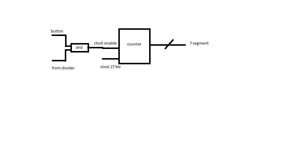
I have a spartan6 FPGA board and am trying to have a pushbutton counter to a 7segment led. If I push button[0] I want counting up, and if I push button[1] I want counting down.
This all works perfectly in simulation, but not in actual on the board.
I know that my code for displaying the number on the 7-segment works perfectly, as it is recycled from a previous project. I know that I need a debouncer in the final version, but it should not matter, as it would just count by more than one.
I'm totally lost as to why this is not working, any direction would be appreciated.
here is the code.
MODULE: main
MODULE: CLOCKDIVIDER (I know this works, as it was given to us, and used in previous projects)
MODULE COUNTER: (works in simulation)
This all works perfectly in simulation, but not in actual on the board.
I know that my code for displaying the number on the 7-segment works perfectly, as it is recycled from a previous project. I know that I need a debouncer in the final version, but it should not matter, as it would just count by more than one.
I'm totally lost as to why this is not working, any direction would be appreciated.
here is the code.
MODULE: main
Code:
module main (button, userclock,sevenLed,cathode);
input  [1:0] button;
input [0:0] userclock;
output [6:0] sevenLed;
reg [6:0] sevenLed;
output [0:0] cathode;
reg [3:0] numSelect;
reg [3:0] out ;
reg [3:0] out2;
wire [3:0] wout;
wire [3:0] wout2;


clk_divider cd(userclock,cathode); //divides the clock

counter counter(button, wout, wout2); //does the counting

//always@(userclock) begin
//out=wout;
//out2=wout2;
//end

always @ (posedge userclock) begin
out<=wout;
out2<=wout2;
end


always @(userclock) begin //what side to show?
	if (cathode==0)
		numSelect=out;
	else
		numSelect=out2;
end


always @(posedge userclock)  //output to the 7segment display
    case (numSelect)
			0: sevenLed = 7'b0111111;
			1: sevenLed = 7'b0000110;
			2: sevenLed = 7'b1011011;
			3: sevenLed = 7'b1001111;
			4: sevenLed = 7'b1100110;
			5: sevenLed = 7'b1101101;
			6: sevenLed = 7'b1111101;
			7: sevenLed = 7'b0000111;
			8: sevenLed = 7'b1111111;
			9: sevenLed = 7'b1100111;
			10: sevenLed = 7'b1010101;
			default sevenLed=0;
    endcase


endmodule
MODULE: CLOCKDIVIDER (I know this works, as it was given to us, and used in previous projects)
Code:
`timescale 1ns / 1ps
//receives a 27 MHz clk on clk_27Mhz and generates a 1 Hz clk on clk_1hz

module clk_divider(clk_27Mhz, clk_1hz);
input clk_27Mhz; // user clock
output clk_1hz; // divided clock
reg [25:0] count; // counter, is bigger then we need in case you wanna play with it
reg clk_1hz; // don't forget the register

initial // This describes what to do as soon as machine turns on
begin
	clk_1hz<=0; // resetting everything
	count<=0;
end

always @(posedge clk_27Mhz) // whenever a rising edge of 27 MHz happens, do:
begin
	// This is just a counter:
	if (count >= 1350)
		count <= 0;
	else
		count <= count + 1;
	// counter ends here


	// this guy decides if it should be 0 or 1
	clk_1hz <= count >= (675) ? 1 : 0;

end

endmodule
MODULE COUNTER: (works in simulation)
Code:
		`timescale 1ns / 1ps
/////	/////////////////////////////////////////////////////////////////////////////
// Company:
// Engineer:
//
// Create Date:    12:31:04 02/15/2011
// Design Name:
// Module Name:    counter
// Project Name:
// Target Devices:
// Tool versions:
// Description:
//
// Dependencies:
//
// Revision:
// Revision 0.01 - File Created
// Additional Comments:
//
//////////////////////////////////////////////////////////////////////////////////
module counter( clk_1Hz, num0, num1 );
input [1:0] clk_1Hz; // 1 Hz clock goes in here
output [3:0] num0; // this would show your ones
output [3:0] num1; // and this one would show your tens

reg [3:0] num0;
reg [3:0] num1;

//initialize the values (optional)
initial begin
num0 = 0;
num1 = 0;
end

always @ (posedge clk_1Hz[0], posedge clk_1Hz[1]) begin

if (clk_1Hz[0] ==1 && clk_1Hz[1]== 0)
	begin num0 = num0 + 1'b1; // increment the ones bit
		if ( num0 >= 10 )
		begin // if it is greater than 9
		num0 = 0; // reset it to 0
		num1 = num1 + 1'b1; // and increment the tens bit.
				if (num1 >= 10) begin // If tens is greater than 9
				num1 = 0; // reset it to 0
				end
		end
	end

if (clk_1Hz[1]==1 && clk_1Hz[0]==0 )
		begin
			if (num0 >=1)
			num0=num0-1'b1;
			else begin num0=9;
							if (num1>=1)
								num1=num1-1'b1;
							else
								num1 = 9;
					end
		end

end
endmodule