Continue to Site

Welcome to EDAboard.com

Welcome to our site! EDAboard.com is an international Electronics Discussion Forum focused on EDA software, circuits, schematics, books, theory, papers, asic, pld, 8051, DSP, Network, RF, Analog Design, PCB, Service Manuals... and a whole lot more! To participate you need to register. Registration is free. Click here to register now.

question on LNA stability

Status
Not open for further replies.

pudding

Member level 2
Joined
Aug 23, 2006
Messages
43
Helped
3
Reputation
6
Reaction score
1
Trophy points
1,288
Activity points
1,605
Hi Guys,
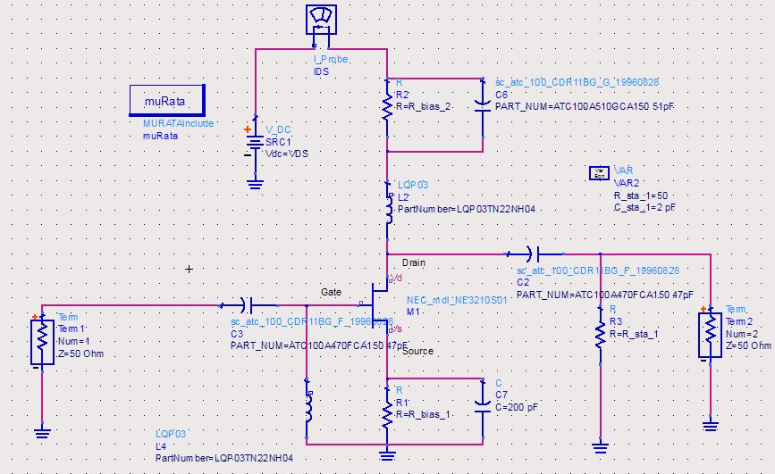
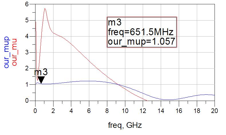
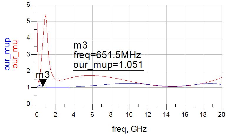
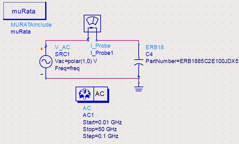
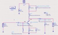
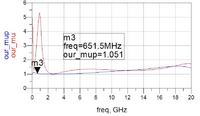
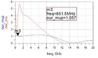
I am designing an LNA at 2.4 GHz. I am a beginner. The transistor is NEC3210S1. When I use an ideal capacitor c7=200pF, the stability is OK(the second picture). But when I changed to a real capacitor model ATC700B201JP300 200pF, the stability became worse(the third picture). I tried several other company's model and got the same results. Another question is since my LNA works at 2.4 GHz, and the mu and mu_prime are less than 1 from 9 GHz, will my circuit becomes resonant? I attached my ads model and murata and NEC kits also. Thanks a lot!

Wufeng


Attachments

  • ne3210s1.pdf
    151.8 KB · Views: 69
  • S_par_VDS_2V_VGS_n0p6V_sta_with_bias.rar
    7 KB · Views: 56
  • murata_library_adse.rar
    887.2 KB · Views: 63
  • NEC_mdl_kit_v1.5.rar
    2.2 MB · Views: 74

This is why important to use with real models and not with ideal parts.
personally i suggest to use with model and not with s par.
try to reduce the value.. let say to 100pF, Xc should be around 0, so 100pF should do the job but check the other parameters...

regarding to the second question theoretically it might oscillate but please check what gain do u have at this point
i think if u working at 2.4G and it happened at 9G it not so bad, of course don't give up and try to fix it
 

When you insert a real capacitor model instead of an ideal cap, you get all of the paracitics that come along with it. A real capacitor can be modeled as a series RLC. The L&C will cause a resonance at ω² = 1 / (LC), where ω=2*pi*freq. Verify that the series resonant frequency of the cap is higher than your operational frequency. Once you pass the SRF, your capacitor will look like a DC-blocking inductor!!

The parasitic resistance is the ESR of the part (Equivalent Series Resistance). Both of which should be in the spec sheet, or can be determined by looking at the plots in the spec sheet.

Start with those two performance measures, and verify that your "real" part will work at these frequencies. Once you know the other "elements" in the circuit (extra inductor and resistor), you can use that knowledge to tune them out of the circuit by adjusting other part values.

Capacitor Modeling article
 
What on earth is first question ?
The first question is why after I substitute the real capacitor with the ideal capacitor, the stability of the LNA became worse?
There is a self-resonance in actual capacitor.

If capacitance value is larger, frequency of self-resonance will be lower.

See Fig.6 of **broken link removed**

So you have to realize 200pF as summation of small capacitors, e.g. 5pF+5pF+10pF+10pF+20pF+50pF+100pF.
With this you can realize low impedance over wide frequency range.

In actual PCB, we implement large capacitance like this.
 
Last edited:
Thanks pancho_hideboo, enjunear and DDavid,
Finally, after I break the 200pF capacitor to 10 20pF capacitors, the problem is solved.

The stability looks the same as the ones with ideal model.
But I still have a question about the capacitor, I did a test on the muRata capacitor

I found out above around 2GHz, the capacitor become an equivalent inductor

But why the model was described as "FreqRange=100MHz-6GHz"? Thanks.

Wufeng
 

Look at the real model. You will find the included Rs and Ls besides the capacitance. For a chip cap there is probably something like 0.5 nH of Ls within the model. The would mean a bypass cap should be about 8.8 pF for 2.4 GHz.

For FET LNA you will likely end up with a terrible S11 for optimum NF with that circuit. Usually a small source inductor is used (0.5 to 2 nH at 2.4 GHz) to get better alignment between optimum noise termination and S11 (optimum gain).

If you think using the real cap model in the sim is tricky, wait until you try to make a PCB for it.
 

But why the model was described as "FreqRange=100MHz-6GHz"?
Even if an operation frequency is 2.4GHz, you have to confirm a stability over wide frequency.

And higher harmonics always exist in circuit even if a driven signal is 2.4GHz.

However you can never see this higher harmonics in AC and SP Analyses.
This is your case.

On the other hand, consider Transient Analysis or HB Analysis.
You surely see higher harmonics effects in these simulation.

So the model have to be covered over wide frequency.
Even "FreqRange=100MHz-6GHz" is narrow where third harmonic of 2.4GHz can not be covered.
 
Last edited:

Status
Not open for further replies.

Similar threads

Part and Inventory Search

Welcome to EDABoard.com

Sponsor

Back
Top