Continue to Site

Welcome to EDAboard.com

Welcome to our site! EDAboard.com is an international Electronics Discussion Forum focused on EDA software, circuits, schematics, books, theory, papers, asic, pld, 8051, DSP, Network, RF, Analog Design, PCB, Service Manuals... and a whole lot more! To participate you need to register. Registration is free. Click here to register now.

Thermistor Comparator Circuit

Status
Not open for further replies.

Shachar85

Member level 2
Joined
Jan 25, 2011
Messages
43
Helped
0
Reputation
0
Reaction score
0
Trophy points
1,286
Activity points
1,638
Hi

I want to build a small circuit which will alert me once the temperature in my fridge goes up. (its an old fridge and it stops working once in 2 or 3 months).

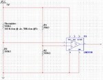
I thought to use a thermistor that will be in the fridge. as shown in the image
Thermistor.JPG

I'm still not sure about the values of the thermistor. So I'll calculate the exact values later. please look at the circuit as the general idea.
The output will be connected to a relay that will switch on the alert circuit (a buzzer and a LED).

I think it should work,but as i'm a beginner in electronics, I thought it would be wiser to be sure before I buy the components.

so what do you say? will it work?

thank you
 

What yo have shown is a basic bridge circuit, however I'm not sure why one of the legs is 50{ whilst the others are 100K.

I suspect you also don't quite understand ordinary Op-Amps when used without feed back.

Op-Amps are also known as "balance" amps in that they have increadibly high DC gain and thus will drive the output hard into the powersupply rail coresponding to which ever of it's inputs is higher.

When the inputs are exactly in balance (ie the same voltage) then the Op-amp output will also be in balance at half way between the two powersupply rails.

Your circuit consists of two potential dividers across the powersupply rail but no method of balancing them with respect to each other or adjusting for temprature.

If you replace the 50K resistor with a variable resistor of about 1.5 to 2.0 times the expected value of the thermistor you will be able to set the circuit such that the Op-Amp output will swing from one rail to another at a given temprature.

The direction will depend on if the thermistor is a Positive temprature coefficient (PTC) or Negitive temprature coefficient (NTC) device. If you get it the wrong way around don't worry just swap the connections to the Op-amp inputs.

Although the circuit will work as shown it is not normal to do it this way because of the high gain the inputs will be very susceptable to noise at the balance point which will make the output crash from rail to rail.

The solution to this problem is to reduce the gain down and then provide a small amount of positive feed back to move one ot the inputs away from the balance point in the desired direction. This effectivly adds hysterisis to the temprature sensing such that it will say flip from -V to +V at 10.1 degree C when warming up but flip back at 10.0C when cooling down.

However to do this you will need to know a lot more about the circuit you are putting it in.

You might however decide to actually go for a tri-state output by using a pair of opticaly coupled LEDs one red and one green whereby the grean is lit for below temp X and the red lit when it's above X with the output oscilating around X the LED will apear to the human eye to be yellow.

You will have to also consider how you are going to couple what is effectivly the "voltage" output of the Op-amp into your indicator if it's input impeadence is less than a couple of hundred ohms.

Hope that helps.
 

thank you for your answer, but I think you missed something about the circuit (or I didn't understand what you meant).

first of all, the upper left resistor is a thermistor. NTC. note that the resistance change from 100Kohm at -4 Celsius (which is the right temperature) to 50Kohm at 5 Celsius (which is when I want to activate the alarm).

the op-amp is not exactly op-amp. Its a 311 comparator, which from what I read, is different from a usual op-amp and designed to act as a comparator. But then again- I only read about it. If you know better, please correct me.
but anyway, I don't think I should use feedback, because then I'll get an amplifier, won't I? and I want a comparator.

The main idea of my circuit is that V- of the comparator gets constant 3.33v (5v divided by 50Kohm and 100Kohm).
When the temperature is right, the thermistor value is 100Kohm and V+ of the comparator gets 2.5V = lower than 3.33V. then the output is VS- which is 0.

When the temperature rises above the alert temperature, the value of the thermistor is above 50Kohm and V+ of the comparator is above 3.33V. then the output is VS+ which is 5V.

This 5V trigger the relay and the alarm.

I hope I explained myself better this time. Please tell me if I got it right, or I'm still missing something.

About the time when the inputs are in balance - It will just activate and deactivate the relay for few minutes(because it means that the fridge broke again and the temperatures will keep rising;-)). I'm not sure it will be so bad if it happens.
If it is, maybe I can connect a capacitor and a resistor between the output and the relay. so that only if the output gives VS+ for 2-3 seconds, the relay will be activated.
 

guys, if anyone can help me with this...

thanks
 

Status
Not open for further replies.

Similar threads

Part and Inventory Search

Welcome to EDABoard.com

Sponsor

Back
Top