Continue to Site

Welcome to EDAboard.com

Welcome to our site! EDAboard.com is an international Electronics Discussion Forum focused on EDA software, circuits, schematics, books, theory, papers, asic, pld, 8051, DSP, Network, RF, Analog Design, PCB, Service Manuals... and a whole lot more! To participate you need to register. Registration is free. Click here to register now.

line follower circuit project

Status
Not open for further replies.

zharie

Newbie level 4
Joined
Mar 3, 2011
Messages
7
Helped
0
Reputation
0
Reaction score
0
Trophy points
1,281
Activity points
1,335
hi guys,
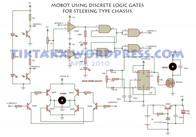
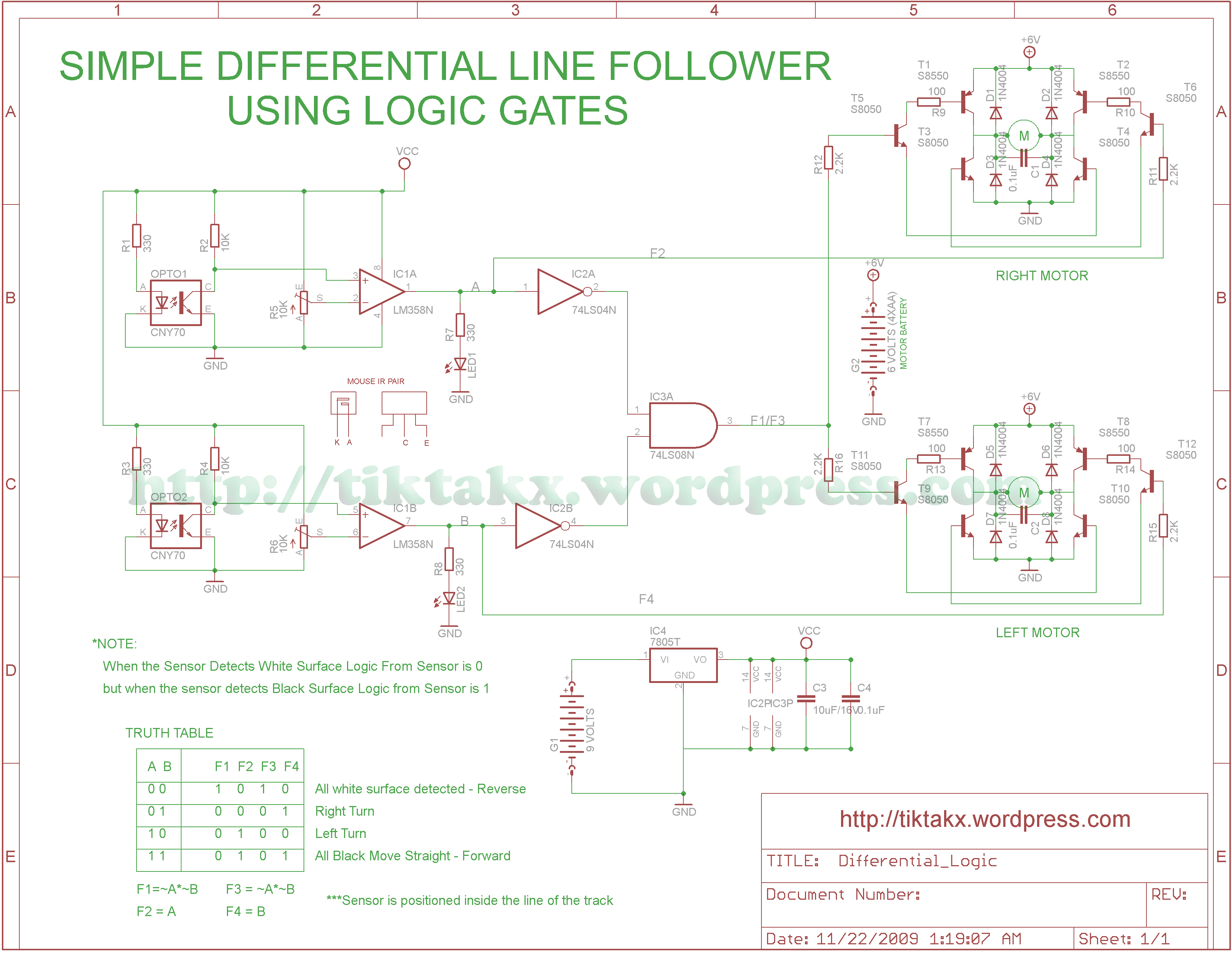
this is my first time to write in here and i really need your help. I'm in the midst of my line follower circuit project. It is actually a transistor based line follower. I'm using a 2N3904 NPN BJT. Does anyone have an idea on how can I include an IC here. my professor wants me to use LOGIC gates and implement it on the circuit. It should be done without the use of microcontrollers. If you have any schematic diagram it would be of great help. I need to submit it on monday. I hope you could help me. thank you very much!
 

Hi. Depends on the type of logic circuits you're using.

A little explanation how to interface a logic circuit to a bjt transistor:

TTL family (74....)
Check datasheet. If open TTL output is collector then you connect output to the transistors base and you only need a pullup resistor.
For ttl output that is NOT open collector, you connect a resistor in series between ttl output and base on the transistor.

CMOS (CD40.....)
Reistor in series between cmos logic output and transistor base.
 

Hi Use a comparator between your sensor and motor drive. Simple isn't it.
LFR Robot.jpg
Thankyou
 
Last edited:

Hi, I just want to share this logic gates based line follower using cheap RC car as the chassis
 

Hi myrick13,

You have observed the original project posted by zharie. It used both the motors to turn. Depending on the angle of turn one motor has to be slowed down and this is done by the transistor of the opposite side. In your case the drive is constant at set speed. Only the steer works for turning which is a problem in certain curves. Hope you have tested this.

Thankyou

PS: You are trying to push the robo while you are turning !!!!!!!
 

yes, that circuit is fully tested, these two line followers use the same circuit as I posted
YouTube - GlueLogic2

These must be the circuit I hope
 

My dear,

Probably you are missing something. Please do pay attention to the second schematic that you have post. This clearly uses two different bridge control for each motor. This means you have independent control of each motor. Where as your first one the drive is constant and you are controlling the steer.

Just try to take a turn while you accelerate a car especially at turns. The car will try to go away from the line due to centrifugal force. The same will happen with your first schematic.

Hope you got it now.

Thankyou
 

Status
Not open for further replies.

Similar threads

Part and Inventory Search

Welcome to EDABoard.com

Sponsor

Back
Top