Continue to Site

Welcome to EDAboard.com

Welcome to our site! EDAboard.com is an international Electronics Discussion Forum focused on EDA software, circuits, schematics, books, theory, papers, asic, pld, 8051, DSP, Network, RF, Analog Design, PCB, Service Manuals... and a whole lot more! To participate you need to register. Registration is free. Click here to register now.

230vac transformer Output to pcb.

Status
Not open for further replies.

hobby12

Junior Member level 3
Joined
Feb 27, 2011
Messages
30
Helped
0
Reputation
0
Reaction score
0
Trophy points
1,286
Location
west midlands-Birmingham
Activity points
1,504
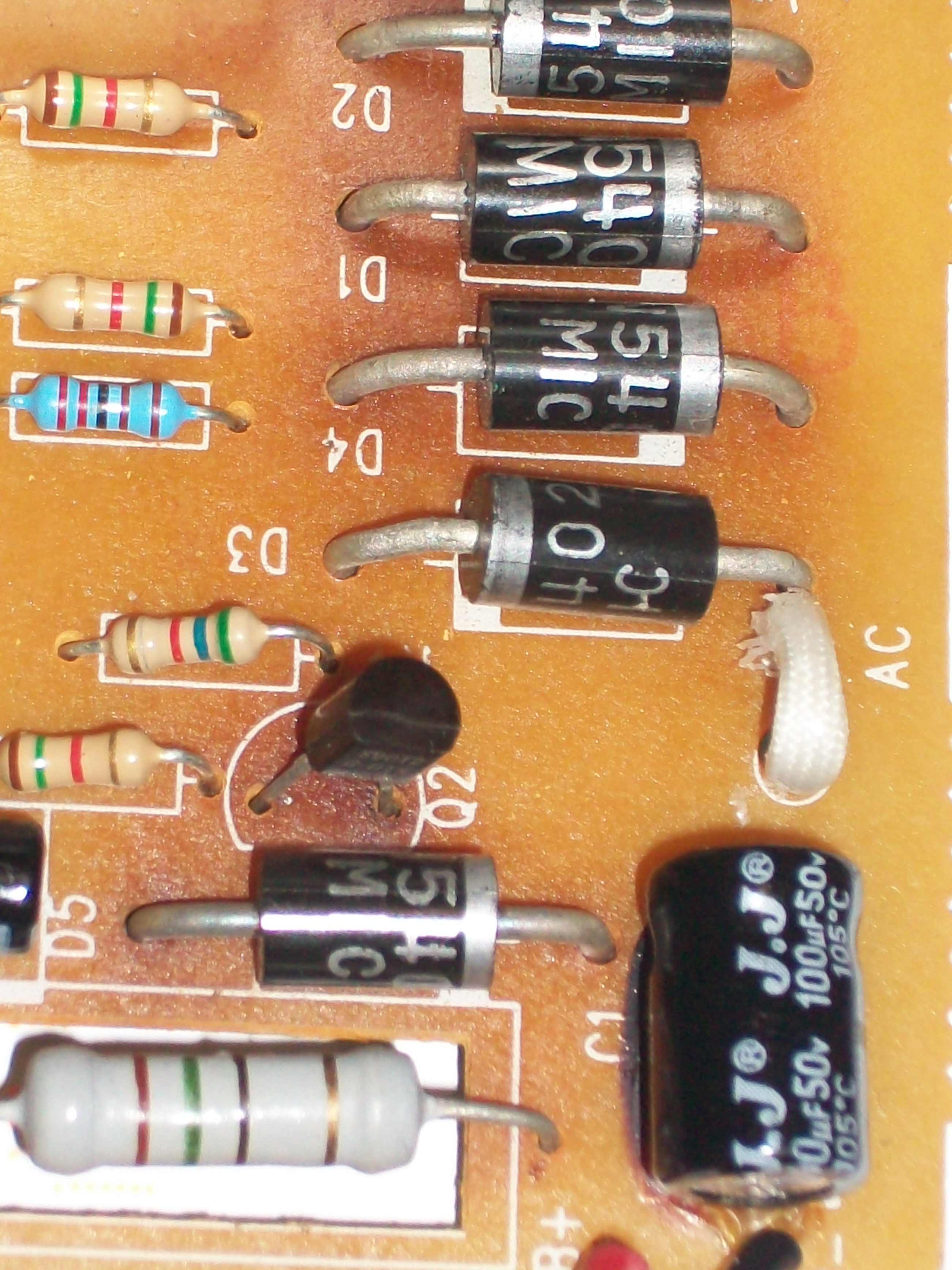
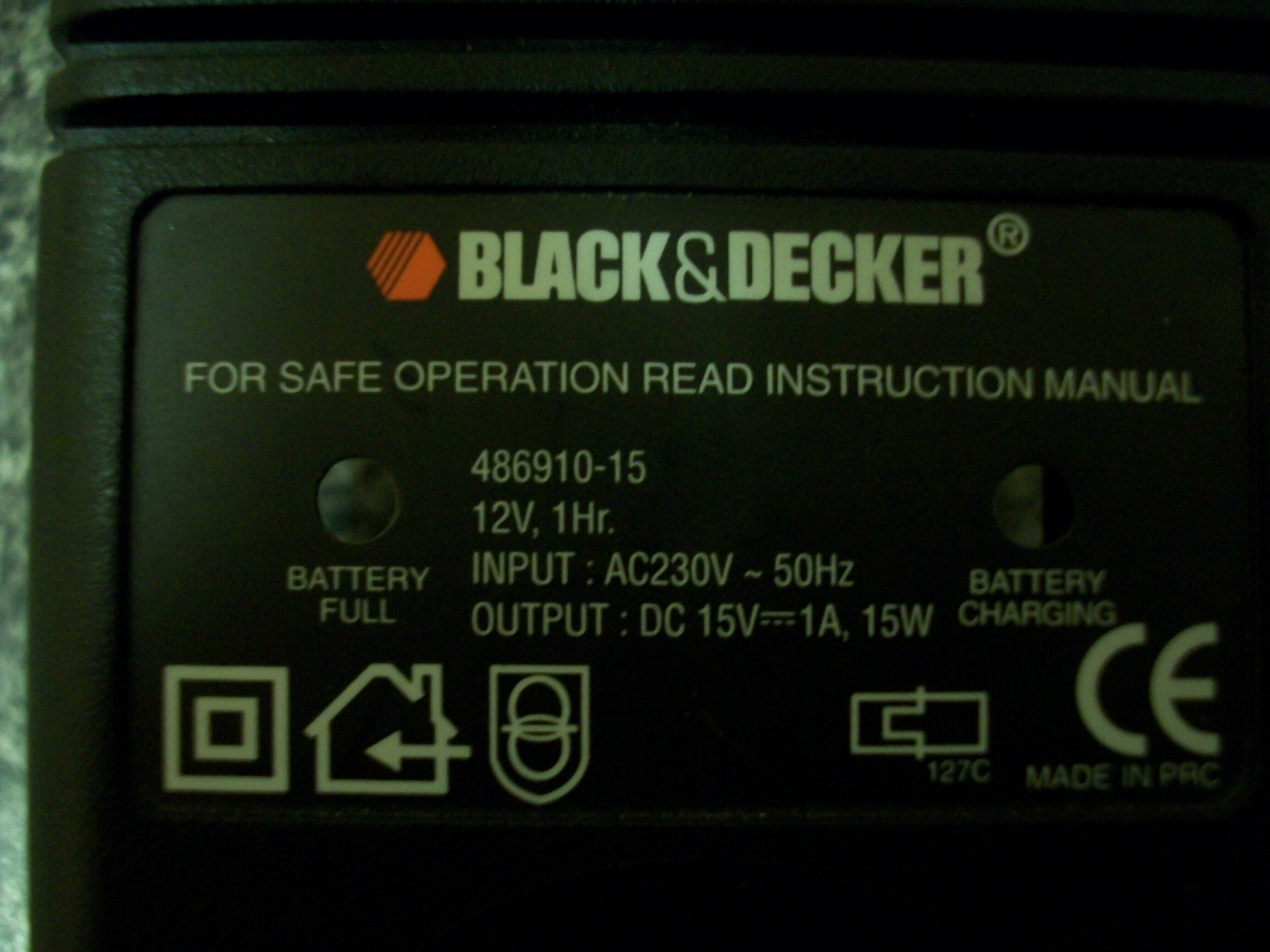
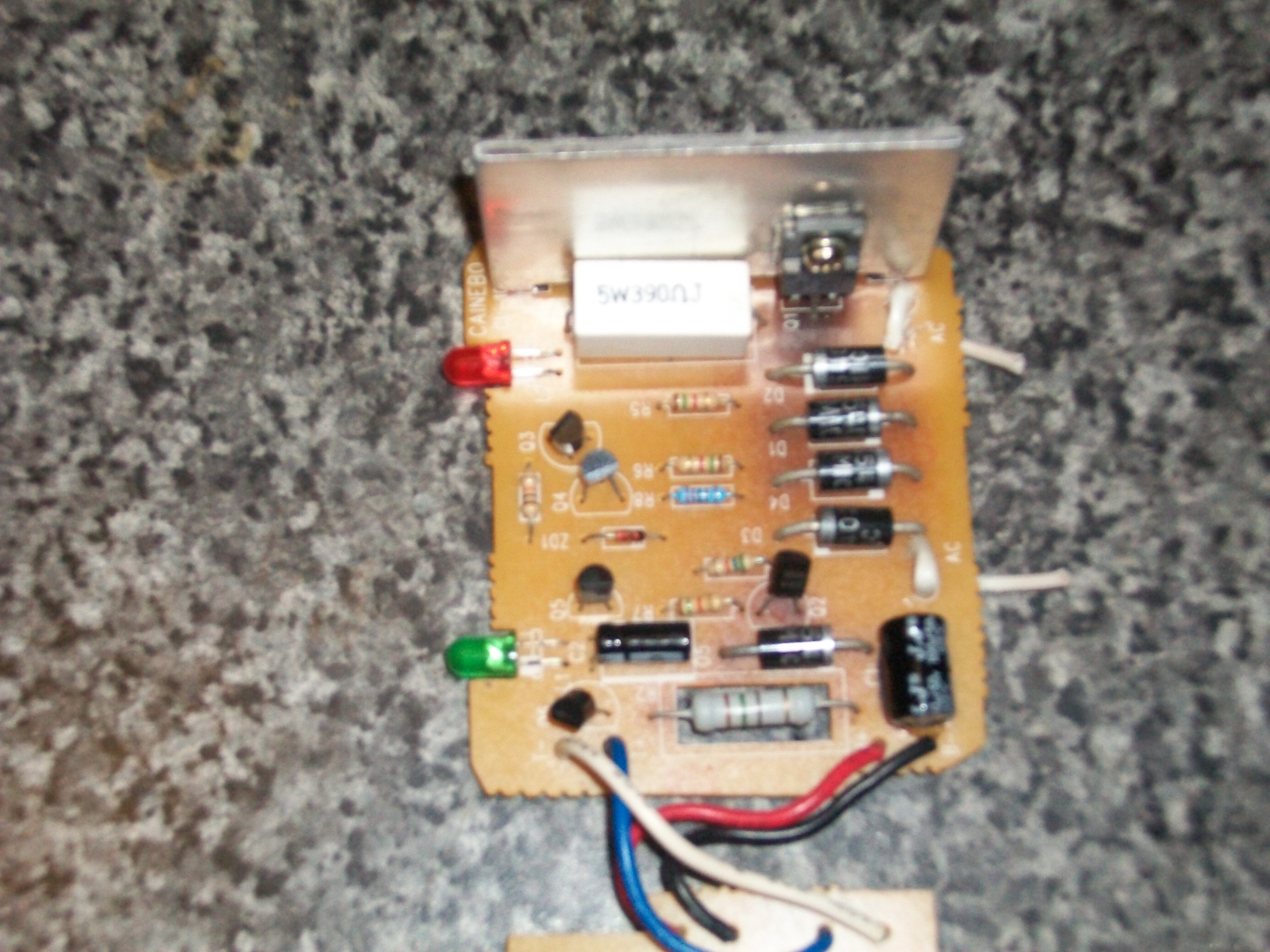
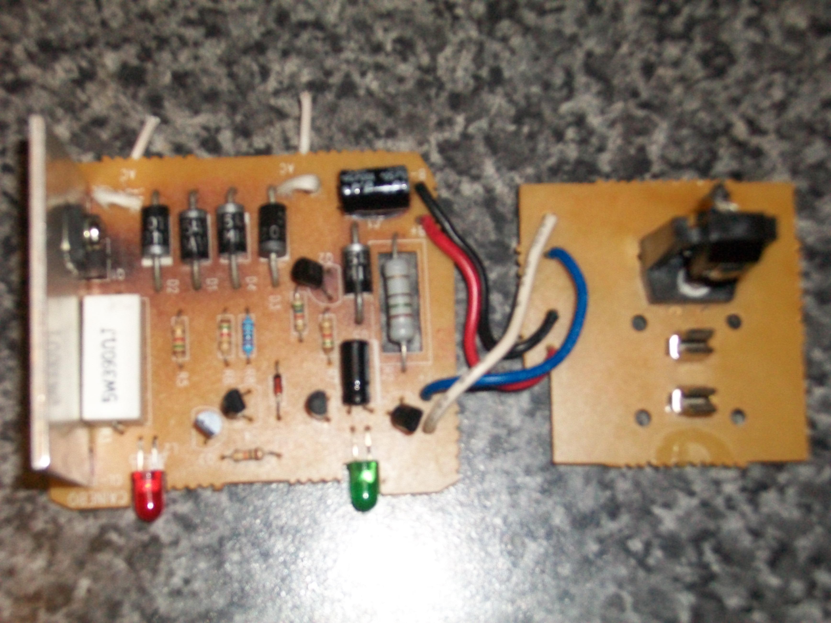
hi, could anyboy tell me the output of a 230v transformer, the two wires from the secondary go to a pcb Ac input, i cannot work out the input from the transformer to the pcb because it has faild. i no the output of the pcb is 15vdc/1A/15W, So my question is what new transformer do i need to purchace. Can anyboy work this out?...:-?:
 

Its impossible to tell with just that information. Can you show a photograph of the PCB or describe the components near to the point where the transformer is connected.

Brian.
 

How you find that tranformer id not working? Check the continuty of Praimary & secondary windings. Any how if u want 15vdc/1A output means... you may go for 12v transfromer(Aprox)... But conform before you put new one.
 

Its impossible to tell with just that information. Can you show a photograph of the PCB or describe the components near to the point where the transformer is connected.

Brian.

this is the pcb, the diodes all say 1n540 mic on them, the capacitor says 1oouf 50v

---------- Post added at 18:42 ---------- Previous post was at 18:39 ----------

did continuty test both primary & secodary no signal. i also tested under 230v mains with same results no output..

---------- Post added at 18:43 ---------- Previous post was at 18:42 ----------

no output from transformer to pcb
 

It looks like a 230v input, the charger is powered from 240v.
If you carefully dig out the outer layers of insulation then you'll find a little black thermal fuse, its probably gone open circuit, temporarily short it and see if the device works, if it does replace the thermal fuse, do not use the device without it, you will have no protection from fire.
 

If you carefully dig out the outer layers of insulation then you'll find a little black thermal fuse
Not necessary that all the transformers will have that fuse.

Looks like you have a voltage regulator on the board (a 3 pin device) do you ? and if so, which is that.
A 12V transformer may not be enough considering the drop out voltage of the regulator.
Check what is the next range available at your local shop. Current about 1A.


Regards
 

I agree, it looks like a simple bridge rectifier circuit and linear regulator. I would guess the other transistors are used to operate an LEDs when the battery reaches full voltage.
First check with an Ohm meter for short circuits across the diodes, they should all measure several hundred Ohms when measured from end to end of each diode. Don't worry if you measure a short from one diode to another, that is normal. The transformer you need is to be rated at more than 15VA (or 15W if that is how it is marked), the higher the VA rating the more reliable it will be but the transformer will also be physically larger.
It looks from the photographs like this is a constant current charger for a NiCad battery pack. Look at the big device on the metal heat sink and note its part number, it is probably marked 7805, if this is the case, you need to add 5V (the last digit in 7805) to the battery voltage to find the voltage you need to produce from the transformer. For example, if it is a 7805 you need 12V + 5V = 17V minimum. In practice, add a few volts for a safety margin, making the transformer a 20V RMS one. Don't add too many extra volts because the excess is turned to heat.

Brian.
 

Question, why dont all electical devices or pcb have a schematic available? these should be made by law to be available to all in case of serious failure. ps a schematic would have solved all my problems, lol....

---------- Post added at 18:10 ---------- Previous post was at 17:33 ----------

hi, sorry im not touching tranformer internal parts as im not to sure what im doing at the moment, would just replace and be safe, this is my problem do i replace with 12vdc or 18vdc transformer, i wont replace untill im 100% sure, better to be safe than sorry, enit,....
 

To answer your first question, I'm sure if you were a serious and qualified contender making an inquiry as to the safety or failiure of one of their products I'm sure B&D would issue you with a schematic, to us however we have little chance.

I made the assumption that you knew the transformer to be faulty, diagnosing that little circuit shouldnt be too difficult using standard techniques.
You can check the trans by measuring the resistance, a few hundred ohms on the primary and a few ohms on the secondary are ball park figures.
 

sorry, but i dont get any ohms resistance from the transformer, or am i doing somthing wrong. I tested it with mains ac and got no voltage output at all, did i test this transformer the right way or not. from what i have learned one reason i might not get output is if the transformer was a swithed type, am i right? im just doing this as a hobby, and not only that i dont like to be told by b&d that it cannot be repaired. i have alot to LEARN, but have to start somewhere,.enit...
 

It is almost inconceivable that both the primary and secondary of the transformer have broken at the same time. This is how you test it:

Resistance tests:

1. Unplug the unit from the power socket.
2. Using a test meter on the Ohms range, first touch the meter probes together and make sure it give a reading of (or very close to) zero ohms. If it doesn't, the meter is set wrongly or not working.
3. put one probe on one pin of the power plug, the other probe on the other pin. The meter should read a few hundred Ohms. The power cable goes to the primary side of the transformer so you are measuring it as though the power cable is an extension of the meter wires.
4. If there is no reading, either there is a fuse in line which is burnt out or the transformer is faulty or the power cable is faulty.
5. If the reading was OK, move the meter probes to the other side (the secondary) of the transformer. This is the two white wires going to the circuit board. Put one probe on each wire. You should see a very low resistance, only a few Ohms. If you do, the chances are the transformer is not faulty.

6. Only do this if the resistance checks 1 to 5 were OK:
Put the test meter on the AC Volts range. If it has several AC Volts ranges, pick the one next higher than 20V.
Plug the power cable back into the wall socket and switch on. Put the meter probes across the white wires again, if you read something between 10V and 30V the transformer is working OK.

Update us on how you get on with these checks.

Brian.
 

ok, first thanks for the reply. I followed step1 to step five,set dmm to ohms, again (nothing), step6 dmm set to ac 20v and above,applied mains voltage tested output (nothing) also tested input there does not seem to be any voltage going in, so i tested mains cable supply to the transformer and that fine. i think its had it. what about the 12v plug in power supply that i have, could i wire that to the pcb and check the output and if it dont match the voltage i need then step the voltage up from there? would that be SAFE to leave runing or not?....
 

I followed step1 to step five,set dmm to ohms, again (nothing), step6 dmm set to ac 20v and above,applied mains voltage tested output (nothing)

Have'nt you read a previous post which warned you "6. Only do this if the resistance checks 1 to 5 were OK:" ?

step6 dmm set to ac 20v and above,applied mains voltage tested output (nothing). what about the 12v plug in power supply that i have, could i wire that to the pcb and check the output

tell me how are you going to get an output at the pcb from nowhere, when you dont get any crap out of your transformer output itself ?
 

It's under 'Location' in the panel at the side of my messages. If you were local I would test/repair it for you.

Brian.
 

hi, not to worry about the repair, thanks anyway. right i took this off the pcb because there was a part of the board sticking up around the base pin that had to be re-solderd. i just thought i would post the photo to see if that help with finding out the input current....thanks.
 

Attachments

  • 4.JPG
    4.JPG
    19 KB · Views: 116

Status
Not open for further replies.

Part and Inventory Search

Welcome to EDABoard.com

Sponsor

Back
Top