Continue to Site

Welcome to EDAboard.com

Welcome to our site! EDAboard.com is an international Electronics Discussion Forum focused on EDA software, circuits, schematics, books, theory, papers, asic, pld, 8051, DSP, Network, RF, Analog Design, PCB, Service Manuals... and a whole lot more! To participate you need to register. Registration is free. Click here to register now.

Detecting ON/OFF status of a switch

Status
Not open for further replies.

2bengg

Junior Member level 3
Joined
Feb 27, 2011
Messages
28
Helped
0
Reputation
0
Reaction score
0
Trophy points
1,281
Activity points
1,498
hiya
im looking to implement something for my final year.
i need to be able to check the status of a switch. i.e is the switch ON or OFF
i figured there are 2 ways to do this,

1. measure the voltage across a switch (if it is 230v AC then switch is open)
2. measure the current after the switch, if there is current flowing the switch is closed.

I need for this to be done using a micro controller.
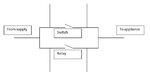
the main idea is Capture.JPG
how can i implement this ?
i need to set it up so that the microcontroller is able to check if there is a voltage drop across the switch or not.
 

Attachments

  • Capture.JPG
    Capture.JPG
    16.8 KB · Views: 118

I don't think it's a good idea to have a direct connection between mains power supply and your micro board. Could be a safety issue.
Measuring the current with a current clamp would be one way to do as you have suggested. You could make a simple clamp by hand winding a coil around the current carrying cable.
 

you could put a relay across the switch and detect if the contact was open or closed. Use an opto isolator for even more isolation?
 
I don't think it's a good idea to have a direct connection between mains power supply and your micro board. Could be a safety issue.
Measuring the current with a current clamp would be one way to do as you have suggested. You could make a simple clamp by hand winding a coil around the current carrying cable.
thanks for your reply,
hmm so if i understand it correctly you are asking me to setup a coil on each wire individually to check if current is flowing through it ?
the entire setup is supposed to include around 5-6 such connections.
so having multiple coil will make the entire circuit look really shabby imo.
could you perhaps suggest another way ?


you could pudt a relay across the switch an detect if the contact was open or closed. Use an opto isolator for even more isolation?
thanks for your reply,
well the circuit is to be designed in such a way that every switch(will be around 5-6 switches) would have a relay across it anyways, so that the switch can be controlled/bypassed by a micro controller.
having 2 relays on each switch would make the project more expensive and complex.
i will have a look into the opto isolator and see what comes up
 

here is my less expensive idea....

in parallel of a switch put up an led and in front of that put an LDR ( insulate the couple from ambient light by using any dark thing like black insulation tape)..
now when the switch is Open the led will glow...
n when the switch is Closed the led will go off....

isn't it simple.... ;-)

also if your switch remains Open for a long time then put the led with resistor in series with switch...


Note: hope u got what i am trying to say...
and if u don't just tell me...
I will put up a circuit pic for you... ;-)

Best of Luck !!
 

thanks for your reply,
well the circuit is to be designed in such a way that every switch(will be around 5-6 switches) would have a relay across it anyways, so that the switch can be controlled/bypassed by a micro controller.
if you have a realy across the switch anyway, so the device can be switched on from a microcontroller, why not remove the mains switch and have a switch as an input to the microcontroller - when the switch is on the microcontroller closes the relay. If the relay has an extra contact you can use that to check it has closed.
 

here is my less expensive idea....

in parallel of a switch put up an led and in front of that put an LDR ( insulate the couple from ambient light by using any dark thing like black insulation tape)..
now when the switch is Open the led will glow...
n when the switch is Closed the led will go off....

isn't it simple.... ;-)

also if your switch remains Open for a long time then put the led with resistor in series with switch...


Note: hope u got what i am trying to say...
and if u don't just tell me...
I will put up a circuit pic for you... ;-)

Best of Luck !!
isn't that basically just using a opto coupler in messy kinda way ?
could you please put up a circuit ? maybe i have misunderstood

if you have a relay across the switch anyway, so the device can be switched on from a microcontroller, why not remove the mains switch and have a switch as an input to the microcontroller - when the switch is on the microcontroller closes the relay. If the relay has an extra contact you can use that to check it has closed.
that would have been possible,however i need the switch to be functional as well. so that either the switch or the relay will be able to complete the circuit.

---------- Post added at 13:52 ---------- Previous post was at 13:28 ----------

maybe i am going about it all wrong and have not been able to explain everything clearly. will be starting a new thread explaining what i need to do in a better way.
could the moderators please delete or lock this thread ?
 

Hi
Just to put a thought on yours. What happens if the switch is closed and the wire is snapped :). Or the other way round what happens if the switch is closed the wires is NOT snapped and the SWITCH itself is NOT working !!!!! :) )).

Thankyou
 

Status
Not open for further replies.

Part and Inventory Search

Welcome to EDABoard.com

Sponsor

Back
Top