Continue to Site

Welcome to EDAboard.com

Welcome to our site! EDAboard.com is an international Electronics Discussion Forum focused on EDA software, circuits, schematics, books, theory, papers, asic, pld, 8051, DSP, Network, RF, Analog Design, PCB, Service Manuals... and a whole lot more! To participate you need to register. Registration is free. Click here to register now.

converting elector video modulator for audio too?

Status
Not open for further replies.

neazoi

Advanced Member level 6
Joined
Jan 5, 2008
Messages
4,123
Helped
13
Reputation
26
Reaction score
15
Trophy points
1,318
Location
Greece
Activity points
36,955
hello I have found this schematic
**broken link removed**
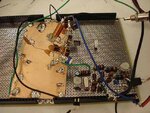
This is a video only modulator.

I have made a 5.5MHz FM oscillator and I wish to conect it's output (capacitor coupled) to a point on the video modulator to mix the two signals and achieve a full audio/video modulator.

What should this point be? I have tried the base of the transistor but the result was not so satisfying. the sound affected the video signal too
 

Connect it to the top of L1 but through a small capacitor (~47pF) so it doesn't load the HF content of the video too much. If that doesn't work, increase the capacitor to say 470pF but put a resistor in series with it (suggest 1K) to isolate the two signals. The level of audio subcarrier should be very low in comparison to the video. I think -18dB is the normally used level.

Brian.
 
  • Like
Reactions: neazoi

    neazoi

    Points: 2
    Helpful Answer Positive Rating
Connect it to the top of L1 but through a small capacitor (~47pF) so it doesn't load the HF content of the video too much. If that doesn't work, increase the capacitor to say 470pF but put a resistor in series with it (suggest 1K) to isolate the two signals. The level of audio subcarrier should be very low in comparison to the video. I think -18dB is the normally used level.

Brian.
Thank you,
It works when connecting to L1 and when using the 47pF coupling capacitor. I had to reduce the 5.5MHz oscillator output level using a 50K potentiometer.

There is another problem now, about audio volume. Visually, on a old analyzer I can see a deviation of about 10KHz in the audio rf. It should be about 25KHz for NTSC. Could this reduced deviation be the audio volume problem?

If yes, then maybe the ceramic resonator I use in the 5.5MHz oscillator cannot be pulled to 25KHz out of it's frequency...
 

You are correct, the amount of deviation is proportional to the recovered audio level. You are probably hearing less than half the sound level you expect.
I'm surprised you are even getting 10KHz deviation if you are using a ceramic resonator. The method used in commercial modulators is to use an LC tuned circuit to generate the carrier then it is fed through a 5.5MHz ceramic filter to remove harmonics and also to restrict the bandwidth if it becomes over deviated. If you really need absolute frequency stability, a PLL locked to a 5.5MHz resonator/crystal would be the best solution.

Brian.
 
  • Like
Reactions: neazoi

    neazoi

    Points: 2
    Helpful Answer Positive Rating
See the last image on this page
**broken link removed**
This is what I have made (using an alternative LC FM oscillator) and it seems to work ok. Stability doesn't seem to be a problem, since small variations in frequency can be tolerated because of the 25KHz FM deviation. Stability of the video carrier is more important I think and this is quite ensured using the crystal oscillator. The audio volume has been improved much but I still have to turn the TV volume too loud to satisfactorily hear it. Any ideas of how to improve this?
 

The modulation is a mix of AM and FM, ideally you want pure FM. The frequency shift you get at the moment is mostly caused by changes in the transistor B-E and B-C junctions acting as tuning capacitors but altering the base current will also change the output amplitude. Your problem is compounded because you are almost certainly not watching on a TV tuned to 27MHz but a much higher harmonic where the inaccuracy of the oscillator is multiplied along with the frequency.

I have made many modulators for point to point TV links which use a 6MHz FM sound subcarrier and they have worked well. One of them is published at: ATV-Projects Gunn Diode Controller ignore most of the schematic, the FM sound generating part is around TR1, you should be able to adapt it for your needs. Note that this design ultimately produces signals at 10GHz so you will not see the main carrier oscillator but you should see where the sound is taken from the modulator through C18.

Brian.
 
  • Like
Reactions: neazoi

    neazoi

    Points: 2
    Helpful Answer Positive Rating
Ah , so you are the author of these nice circuits I have found some years ago on the web :) This was among the first websites that let me begin on microwaves, congrats!

The stability is indeed worst when multiplying, but the quartz crystal is ultra stable (let temperature variations alone) and the stability could be much better even on the 10th harmonic compared to a UHF LC oscillator. For a TV signal this is ok, I am actually rinning this oscillator now for 2 days continuously and I have not found any stability issues.

>B-E and B-C junctions acting as tuning capacitors...

I am not very confident of how the bfr91 is actually working. I thought it was working as a mixer, mixing the 5.5MHz with 27MHz? But then what about the harmonics?
I will try to change the 2n4401 with another one of different capacitance to see how this will affect the sound volume, It might do the trick.

---------- Post added at 13:55 ---------- Previous post was at 12:37 ----------

Ok I have tried the BC549 transistor for the 5.5mhz oscillator and it gave more than 50% of volume! No other undesired effects on the video signal.
I continue trying more transistors to find the optimum.

It seems the video signal is affected only by the amount of 5.5 MHz RF injected to the modulator, not the audio deviation.
 

Thank you!

In an ideal situation, you would multiply the 27MHz up to TV frequency first then add the 5.5MHz to it. The problem with this simple modulator is it produces a wide spectrum of frequencies consisting of multiples of 5.5MHz, multiples of 27MHz and all the +/- mixing between them. The one you are trying to use is the 10th harmonic + 5.5MHz which is perhaps 1% - 2% of the total output.

The 5.5MHz and 27MHz do mix to produce 21.5MHz and 32.5MHz but that isn't what you really want to happen. The 5.5MHz is actually mixed with the video and becomes a second modulating signal, bear in mind the video itself goes from DC to about 5MHz.

There are two reasons why the video is affected by the injection level, firstly 5.5MHz is visible on the screen as a fine dot or line pattern which degrades the underlying picture and secondly, some of the video signal is absorbed back into the 5.5MHz oscillator circuit, this shows as a fall in HF response, making sharp edges look blurred.

Brian.
 
  • Like
Reactions: neazoi

    V

    Points: 2
    Helpful Answer Positive Rating

    neazoi

    Points: 2
    Helpful Answer Positive Rating
This is really helpfull! I have not found any documents explaining this technique and I was allways wondering why some modulators connect the baseband audio and video together. I was aware only of the mixing technique of the high frequency rf with the 5.5MHz audio carrier.
Do you think I sould try this method instead? Maybe by adding a single mixer diode at the output of the modulator to mix the 5.5MHz with any of the harmonics produced from the modulator, instead of mixing the baseband signals at the base of the bfr91? What do you think?

A little feedback about the achievement:
I have managed to have this picture on uhf **broken link removed** as musig plays at the same time. This is not too bad and it actually is better than some old commecrial transistor modulators. The audio level is much improved and the modulator is sensitive to lower input audio volume (in comparison with olr transistor commercial tunners I have tested), which is good to my application.
 

Well done, the picture looks very good.

The method used in commercial AV modulators (Astec etc.) is to generate the VHF/UHF signal at fundamental frequency then use a diode mixer to mix the combined video signal and audio carrier together. For example the UHF oscillator might be at 500MHz and the mixer would produce 505.5MHz and 496.5MHz. Doing it that way prevents many of the other mixer products causing interference. The second harmonic is much higher in frequency so a simple LC filter can remove it. From the TV point of view, it doesn't matter that the signal has two sidebands because the IF filters are narrow enough to block the one you don't want.

Are you using a video pre-emphasis circuit ahead of the modulator?

Brian.
 
  • Like
Reactions: neazoi

    neazoi

    Points: 2
    Helpful Answer Positive Rating
Well done, the picture looks very good.

Are you using a video pre-emphasis circuit ahead of the modulator?

Brian.

Thanks Brian!
No I do not use any pre-emphasis, neither for video nor for audio. The signal you see in the picture is taken from an analogue vhs tape camera, so these are about the input levels used. The picture is taken from the modulator adjusted on the 460MHz (17th) harmonic.
The audio was very "shy" but when I replaced the transistor with the bc549b the audio volume was much much better. Ok for the computer application, but it is about the half volume of that of a commercial transistor modulator (just to give a relative measurement). Still has some window for improvements, but I do not know what are the (transistor) parameters that I need to look at to achieve better fm deviation at the same audio input level. Could it be the RATIO of the B-C B-E capacitances? Experimentally I found that this ratio is greater on bc549b but I do not know if this is what matters.
 

The relationship between B-C and B-E capacitance is probably very complicated, especially when the whole circuit is oscillating as well. You could try these ideas:

1. drop the values of the two 1nF capacitors to 100pF, it should still oscillate but the transistors capacitance will play a greater part in the tuning.

2. replace the variable capacitor with a fixed one of 1nF and connect a varicap diode from it to ground, anode side to ground. At the cathode end where it joins to the 1nF, put a 100K resistor to ground and a 100K resistor to supply and a 10K resistor to the audio.This should bias the diode at about half supply voltage and the audio will vary it's capacitance. You need to isolate the audio through another capacitor (100nF) so the audio can't change the varicap's DC conditions. This method will should also give less AM change on the output level.

Brian.
 
The picture is taken from the modulator adjusted on the 460MHz (17th) harmonic.
Saying the modulator is generating a considerable amount of high order harmonics is just another word for telling it's rather non-linear and thus involving intermodulation of audio and video carrier. So won't you have to wonder about a reason for bad video and audio quality. Analog TV transmission components have to be linear for good quality.
 
  • Like
Reactions: neazoi

    neazoi

    Points: 2
    Helpful Answer Positive Rating
Saying the modulator is generating a considerable amount of high order harmonics is just another word for telling it's rather non-linear and thus involving intermodulation of audio and video carrier. So won't you have to wonder about a reason for bad video and audio quality. Analog TV transmission components have to be linear for good quality.

Sure, I do not disagree on this. The result is very satisfactory though even with this two transistor harmonics circuit. Note, the video and audio quality are very fine for an analogue TV modulator, the only point to consider is the little less volume audio for the time being. Components tolerances and layout is not critical at all as the only really vhf/uhf part is the harmonics diodes and the little coil at the right hand side of the circuit. Coils are easy to make and no hard to find transformers used. I think it is interesting to the poor man homebuilder :)
I have managed to make very small air coil instead of the commercial 1uH for the 5.5MHz, which worked fine. I will update the site asap.

Next days I will try the changes betwixt has proposed so I find the optimum point for the audio modulation.
 

Betwixt has basically mentioned the same. I just wanted to clarify, that particularly the harmonic generation method of the Elektor modulator inimplies some quality problems. Strictly spoken, it's already contradicting the concept of linear video modulation, but it's surely worse when the audio carrier is added. Linear AV modulators have been previously available as ICs, e.g. from Philips/NXP. I don't know if they are still manufactured these days. But I think, that the effort for a discrete transistor design won't be much higher, may be a three transistor + diode mixer circuit.
 
  • Like
Reactions: neazoi

    neazoi

    Points: 2
    Helpful Answer Positive Rating
Yes this is absolutely correct FvM. At the time of adding the audio stage I was basically started to think if this was allready getting too complex with this addition. I wanted a simple circuit with an acceptable result. The absense of a difficult to find 5.5MHz transformer, the easy to find components, the ability to transmit both on uhf and vhf and the high quality video and good audio signal on some of the harmonics (higher than some old commercial transistor modulators I have tried) experimentally proved it is not a prohibited modulator to go anyway.

Nevertheless I would be very interested in trying a 2 or 3 transistor approach that uses one of them as FM modulator, the other one as video modulator near the actual transmit frequency, and the last one as a mixer to mix the carrier with the subcarrier in order to produce the final complete signal.

Unfortunatelly all the simple circuits I have found on the net are mixing the audio and video and then feed them to the final transistor (or amplifier).
If you have ever seen such a circuit it yould be great to know.
Thank you all very much

I have attatched a vew of the up to date circuit just for interest
 

Attachments

  • aaaa.jpg
    aaaa.jpg
    60.1 KB · Views: 105

Status
Not open for further replies.

Part and Inventory Search

Welcome to EDABoard.com

Sponsor

Back
Top