Continue to Site

Welcome to EDAboard.com

Welcome to our site! EDAboard.com is an international Electronics Discussion Forum focused on EDA software, circuits, schematics, books, theory, papers, asic, pld, 8051, DSP, Network, RF, Analog Design, PCB, Service Manuals... and a whole lot more! To participate you need to register. Registration is free. Click here to register now.

Do transformers obey ohms law..

Status
Not open for further replies.

SanjKrish

Member level 3
Joined
Feb 6, 2011
Messages
67
Helped
1
Reputation
2
Reaction score
1
Trophy points
1,288
Location
India
Activity points
1,855
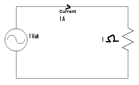
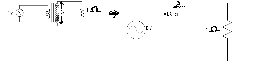
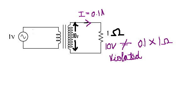
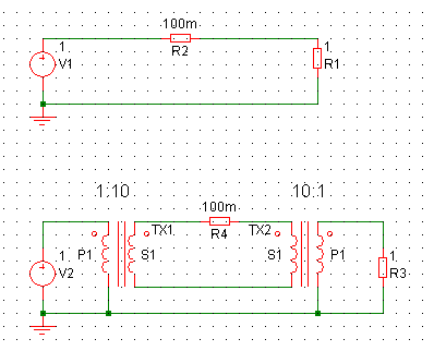
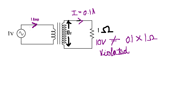
I read that a step up transformer increases the voltage decreasing the current..
But by ohms law when voltage is high the current flowing through it should also be high

The two statements are contradicting.. Can anyone help me understand this..

If I were to compare it with water analogy.. more pressure should cause more water to flow in the pipes... but what a transformer does is, it increases the pressure but decreases the water flow...

Plz help me understand..
 
Last edited:

A transformer converts the energy (or power) from on form to another. They are not perfect so some power is lost, but if the voltage is increased the current available must be lower otherwise you would have gained some energy/power. Nice if it could be done, but the law of conservation of energy says the total energy must be the same.

Ohms law is not really relevant. That describes the function of a resistor.

Keith
 

The simple answer is, that a transformer doesn't obey ohms law because it isn't a resistor. Also your water analogy is meant for resistors. You would need a different one for the transformer. E.g. a watermill driving a high pressure water pump.
 

Ok..You say that a transformer keeps the power constant on both sides..
Agreed..

But what by brain refuses to accept is this..
Question 1
Say suppose I have a huge fan.. which can run in a wide range of voltages from 20V to 20,000V..
If I put this fan across the terminals before stepping up, which is 20V, should I expect the fan to run slower...
If I put the same fan in the secondary after stepping up, which is 20,000V, will it run faster
OR
since the power is same on both the cases, will the speed of the fan in both the cases will be the same...


Second Question
While transmitting power we minimize the current in order to minimize the power loss in a transmission line which is equal to p=I²R..
My doubt is that, P is also equal to V²/R, which says if we increase voltage too, the power loss should be more..

Plz excuse me if my question is very dumb.. Can u give me any analogy to understand this..
 

1)speed of the fan will be the same, just in first case you have to have 20V AC motor and in second one 20000V AC motor
futher explanation - you have 20W bulb which is 20V 1A rate and you have another 20W bulb which is 200V 0.1A rate
then you have transformer 1:10 and AC power supply with 20V AC output. connect first bulb to power supply, or connect second bulb via transformer - they will give you same amount(well say "same" and dont think about lost in core) of light

2)R is for active resistance, but there is reactive resistance in the coils(transformers etc) so story is little bit different
 

It is no good inventing implausible devices to try to explain the problem - you will tie yourself in knots by introducing devices which break the laws of physics. While water pressure and flow are used to explain voltage and current you need to be careful to make sure any analogies are valid otherwise they simply cause more confusion. I prefer to understand the underlying physics rather than try to create analogies.

I am not sure where your second question is directed. Are you describing electricity power lines where voltage is very high to minimise the cable loss? If so, you are confusing the resistance of the load and the resistance of the cable. Maybe some numbers would help. If you apply 1V to a 1 ohm load it will take 1A so the power is 1W in the load. If you used a transformer to transmit the power at 10V you would only need 0.1A which would still be 1W. You would need to use another transformer to get the voltage back to 1V to power to 1W in the 1 ohm load.

Now consider what happens if your cable has 0.1 ohms of resistance. If you were sending the power through the cable at 1V, you would lose 0.1V due to the 0.1 ohm if the current was 1A. That is 0.1W lost.

If you used 10V to send the power, the current is only 0.1A so the loss is 0.01V in the 0.1 ohm cable resistance or only 0.001W. So, by making the voltage 10 times higher and therefore the current 10 times lower we have made the power loss 100 times lower.

Keith.
 

you need to be careful to make sure any analogies are valid otherwise they simply cause more confusion
Yes. I won't suggest other analogies rather than saying, if you try to use an analogy, you have to use a different one. A physically correct analogy respectively equivalence is possible in some cases, but of course doesn't simplify the calculation. If at all, I would do it the other way round, e.g. to analyse a fluidic or thermal problem with an electrical solver.

To answer the Questions yourself, you have to look at the discussed problems more exactly. Draw a circuit with source, load, wire resistances, mark voltages and currents. Then everything can be calculated. If you are writing equations involving R, consider if you are talking about the load or the wire resistance.
 

SanjKrish,

First off you have to accept a couple of things,

1, All physical tranducers are imperfict and have losses.
2, All theoretical devices are perfect and the losses are treated seperatly as passive components.
3, Some components are theoreticaly just resistance.
4, Some components are theoreticaly just reactive.
5, Theoreticaly a reactive component is either capacitive or inductive.
6, In practice all components are part resistive, part capacitive, part inductive.

A simple straight wire has resistance, some inductance and some capacitance, both of the capacitance and inductance values are effected by other components adjacent to the wire. This is usually expressed as a coupling factor, that is some of the energy is transfered from the wire to the adjacent component. The coupling factor is largly dependent on the physical parameters of both the wire and the component and secondarily on the frequency of the energy.

This is because any electrical energy (current colombs) flowing through the wire generates a field around the wire (look up Lenzes law). This field has two usually orthagonal field vectors the H and the E components (in theory they are seperate fields but in practice we don't see one without the other).

The energy from the field around the wire can only couple effectivly into the adjacent component if the field changes intensity (I'm waving my hands here to avoid getting into field theory).

Now as I said above a wire has all three bassic types (R/L/C) of component and the relative amounts are dependent on the physical arrangement. If you flatten the wire to form a metal plate it's capacitance goes up although the resistance stays (broadly) the same. If however you coil the wire up it's inductance goes up a lot (and the capacitance as well due to the loops coupling to each other).

The reason the inductance goes up a lot is it is effectivly concentrating the magnettic component of the field into a much smaller volume (volume varies by x^3 of the diameter).

Now if you think about two wires wound as coils and in the same orientation they have a physical physical closeness that allows their fields to couple together. The closer the windings are to each other the more efficient the coupling. Part of the coupling is dependent on the effective inductance of the coil and this is strongly effected by certain meterials changing the effective reluctance of the space the magnetic field is in. The materials are generaly based on iron or chromium or other similarsimilar metals.

From this it can be seen that a transformer is not a "Direct Current" transducer but an "Alternating Current" transducer, and that like all transducers it is bidirectional that is the output load effects the input load as seen by the generator driving it.

However as the input and output windings/coils have resistance. For the input winding this is seen in series with the winding across the generator. For the output winding this is seen by the load impedance across it. Thus although the resistance of the windings is only seen at DC to the respective sides as the coupling increases at AC frequencies the output winding impedance is seen by the generator. In both cases the resistance represents a loss in the transformer (therefor it can not be perfect) and the energy is effectivly converted to heat. When transformers are built they are tested with very low voltage DC to assess the winding resistance, they are then tested with a very high DC voltage applied to one terminal of the input (primary) winding and one terminal of the output (secondary) winding to assess the leakage resistance between the windings.

Now if you think about the field generated around the primary winding it's intensity is bassed on the current in the winding and the number of turns. That is the same field intensity can be achived with different numbers of windings and different currents. As we are talking about theoreticaly perfect transformers this field represents the energy put into the winding by the source generator. If you view the winding as a storage device the energy has to go somewhere. If the other winding is effectivly invisable without a load connected across it the energy can only be returned to the source generator as what is described as the "back Electromotive Force (EMF, it's called "electromotive force as it was originaly associated with DC motors)". This Back EMF opposes the generator therefore the generator effectivly sees and infinite impeadence as all the energy is returned to it.

However if a load is put on the secondary winding some of the energy couples into the load and this represents a (useful) loss of energy from the field, therefore the energy returned to the generator is reduced by the amount transfered usefully to the load thus the generator nolonger sees an infinate load and starts putting energy into the load.

Now importantly you need to remember that energy against time is power and this is independant of current or voltage (ie energy is energy in whatever form). However energy is tied to current via the amount of charge (Coloumbs) transfered in a given time. Thus you can talke about the transformer in terms of energy transfered in a given time, but also in the charge transfered as well (thus the transformer looks like a transmission line of near zero length). However the coupling between the input and output windings is via the field stored and coupled between the windings.

If you look back I indicated that the intensity of the field was related to the current (charge per second) and the number of windings. NOW IMPORTANTLY the field around both coils is the same. Thus if the number of turns in the windings is different then the current in the windings must be proportianatly different that is in normal operation the currents in the primary and secondary windings are related by the ratio of the turns.

Now as I said the generator sees the output load via the loss in the energy that gets returned to the generator, thus as energy against time is power this loss is the power is that transmitted to the load.

Now if the load is a pure resistance it follows from I^2R = P = VI that the change in the ratio of the currents reflects in the change in voltage from across the generator terminals to the voltage across the load terminals.

HOW EVER THIS VOLTAGE CHANGE ONLY APPLIES TO PURE RESISTIVE LOADS, if the load is reactive you have to return to working out the effecive currents and how they reflect back through the transformer. In the case of reactive loads the actual signe of the reactance gets inverted, thus a capacitive load is seen as an inductive load across the generator.

I hope this helps you start on understanding a little more about transformers.
 
  • Like
Reactions: arthur0

    arthur0

    Points: 2
    Helpful Answer Positive Rating
    V

    Points: 2
    Helpful Answer Positive Rating
Thankyou lurchman, for ur deep insight into transformers..

keith1200rs , you were very close, but I was lost here...

According to what you said, V=1Volts, R=1Ω.. The circuit would look like this
5_1297356054.gif


The current flowing through the circuit should be I=1Volt/1 ohm = 1Amp.. As u said.. Perfect till now...

Now, in the second case, we use a step up transformer and increase the voltage to V=10 Volts and the circuit would be like this


I have drawn the second circuit, which produces the same voltage but without the transformer..
In the circuit V=10Amps, R=1 ohm and therefore I should be I= 10*1 = 10Amps..
I took resistance as constant and the current depends on the value of resistance... Therefore the power dissipated should be 10 * 10 = 100Watts.. (cannot be... I know..)

But If I were to take as you said.. when V = 10V, I=0.1A then if I plug the resistance in my circuit V=IR relation is not satisfied..
V=IR
10 ≠ 0.1*1
The circuit for this would be


I believe resistance is what draws current.. and current cannot be fed to a resistance or load whatever..
Do you take resistance as a variable?? If I go to a store and ask for 1Ω, the 1Ω is 1Ω only for 230 Volt supply... and not for other voltages...
Where am I getting wrong??
 
Last edited:

The scenario I was trying to describe, based on your comments about "transmitting power" which I took to mean main power distribution, is the one shown below:

20_1297358795.gif


I may be trying to explain the wrong thing, but here goes.

So, R2 and R4 are the cable resistances. In the simple circuit at the top the power lost in R2 will be a little less than 0.1W because the total resistance is 1.1ohms not 1 ohm.

In the second scenario, the voltage is boosted by a factor of ten before transmission and then dropped back down again before the load. So, the current through R4 will be lower than through R2 and so the power loss will be lower. The final power in the load will be almost the same (the difference will be due to the different losses).

If you were to use just one transformer - the step-up one, the power in the load would be considerably higher.

One thing to remember is that a perfect transformer reflects the load impedance, based on it's turn ratio. So, if you put a 1ohm load on the secondary of a 1:10 step-up transformer the primary will see 0.1 ohms.

Keith.
 
  • Like
Reactions: lurchman

    lurchman

    Points: 2
    Helpful Answer Positive Rating
    V

    Points: 2
    Helpful Answer Positive Rating
Keith, I'm very sorry, I'm still not able to understand...
Ok.. Just tell me this alone....

What's wrong with this circuit


What should have been the values of current and voltage to make the circuit satisfy the relation??
 
Last edited:

Sorry, I am sure it is me making things more complicated than they need to be.

In your circuit, the mistake is drawing "1 amp" from the voltage source. The current from the voltage source will be determined by what load it sees.

The voltage from your voltage source will increase to 10V in the secondary - as you have shown. So, the current will be 10A (=10V/1ohm) and so the power will be 100W. The current on the primary side will be 100A! The 1 ohm load impedance on the secondary is "reflected" or "transformed" to the primary side where it looks like 0.01 ohm due to the 1:10 turns ratio. The resistance is transformed by the turns ratio squared so 1:100 not 1:10.

Keith
 
Keith , your great...
I'm very happy.. Infinite thanks to you..
I understood how it works...

The transformer increases the current on the primary side, making the resistance look smaller...
One last question, Keith.., In the circuit below


It seems like higher the resistance, lower is the power loss...
Where am I wrong???
 

If the voltage is fixed and you increase the resistance then yes, the power will decrease. What you have drawn is obeying ohms law - no transformers.

Keith
 
in case of step up transformer the secondary coils for step up are more than that of primary coil so because of induction the secondary coils are generating the more voltage than that of primary coils. Now due to resistance of coil as the length of step up coils and other factor are involved we see current decrease at the other end.
 

    V

    Points: 2
    Helpful Answer Positive Rating
SanjKrish,

The important thing to remember is the the transformer is a current to current transducer and it works by converting the current to a magnetic field in an inductor (/coil/winding) and the field intensity is dependent on the value of the current and the value of the inductance. The value of the inductance is determined by the physical properties of the winding and the core around which it is wound.

As the inductor stores energy in the magnetic field any conductor in the same field will as the field changes take energy from the field.

Thus if there are two practicaly identical windings (same number of turns etc) around the core you would expect the current from one to produce a field bassed on current/turn in the core and the same field to induce a current/turn in the secondary winding.

Now if you change the number of turns in the secondary the field from the unchanged primary is the same but the current/turn ratio in the secondary is different.

Thus if you have ten turns in the primary and 1amp of current, you will in a one hundred turn secondary see one tenth ot the primary current. Likewise if the secondary has only one turn then you would expect to see ten amps int the secondary.

If you don't remember this you will have a great deal of trouble understanding how "current transformers" used in certain types of power supply and measuring instruments work.

Also as the winding is effectivly a "dead short" on the generator the only thing stopping it shorting the generator out is the behaviour of the winding as an inductor.

Thus the inductance of a winding is important depending on the frequency of the generator. As a very rough approximation it should be about 4:1 on the load impeadence.
 

    V

    Points: 2
    Helpful Answer Positive Rating
yes they do.but not EXACTLY!!!! ohm's law says:"voltage and current are in direct LINEAR relationship for a conductor"...here LINEAR is important!!!!
in step up transformers,VS as well as IS increases!!! but not linearly!!! so they are in direct relationship....but!! NOT in linear relationship....!!!
now one may ask..if both VS and IS are increasing,it means power output in more than power input which is against the law of conservation of energy....so ANSWER lies here........
power equation for transformers is:
VP * Ip =VS * IS
now in step up as Vs and Is increase...Ip also increases(generator must be able to provide extra Ip)...which means power input increases...and equation remains valid...
 

    V

    Points: 2
    Helpful Answer Positive Rating
Thanks ali ghafoor.., for you detailed explanation...
Still a pesky question is there in my mind...

Our ultimate use of transformer is to reduce the power loss in Transmission lines... But in the circuit below


It so seems that the circuit with the transformer dissipates more power..
I am totally convinced that a transformer makes the resistance look less... which is good...

but how come a lesser resistive circuit dissipate more power????
 
Last edited:

Comparing apples to oranges...
You have to compare cases with same power transmitted to the load, not with same load resistance.
 

SanjKrish,

Stop getting hung up on V=IxR on transformers when crossing over from one winding to another.

As I and others have told you think about "energy" being transported in a given "time" as "power".

Basic physics tell you that energy cannot be created or destroyed, just changed from one form to another and to move from a cohearant form to an incohearant form via the process of entropy.

As has been mentioned the load the generator sees is not the DC impeadence of the winding (this is fractions of an ohm in many cases) but the AC impeadence created by the effective inductance and thus the Back EMF that opposes the generator.

It is the same "Back EMF" that stops the near dead short of battery by a DC motor (in this case as the motor turns it also acts as a generator which opposes the current from the battery)

The energy stored in the magnetic field from a winding can only leave it if there is some method of coupling energy out of it and it is realy this you need to understand.

If not you will not understand how the back EMF from a simple coil can reach hundreds if not thousands of volts when the DC supply switch to it is opened (which is part of the principle of a car ignition system).

Put simply as the magnetic field collapses it tries to induce a current into the wire of the windings. As the circuit is effectivly open the load can be considered to be very very high thus to move the same energy as stored in the field the coresponding voltage must rise until a charge flows taking the energy out of the field.

Now I could trot out all the formula relating to this but unless you let go of the notion of just trying to understand what is going on in a transformer with just the instantaneous Voltage, Current and Resistance in the winding you will not understand how inductors let alone transformers work.

And in the case of a transformer it is two (or more) windings that (usually) only share the same physical volume where a magnetic field exists which is where the energy is stored.
 
  • Like
Reactions: arthur0

    arthur0

    Points: 2
    Helpful Answer Positive Rating
Status
Not open for further replies.

Part and Inventory Search

Welcome to EDABoard.com

Sponsor

Back
Top