Continue to Site

Welcome to EDAboard.com

Welcome to our site! EDAboard.com is an international Electronics Discussion Forum focused on EDA software, circuits, schematics, books, theory, papers, asic, pld, 8051, DSP, Network, RF, Analog Design, PCB, Service Manuals... and a whole lot more! To participate you need to register. Registration is free. Click here to register now.

ATmega16 ADC interfacing.

Status
Not open for further replies.

yokohama

Member level 3
Joined
Dec 29, 2010
Messages
55
Helped
4
Reputation
8
Reaction score
4
Trophy points
1,288
Location
Algeria
Activity points
1,659
Hi everybody,
I'm new in avr programming, and here is my problem:
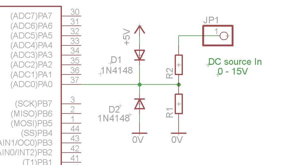
I would like to sample a dc source who varies from 0V to 15 Volts, and we know that the adc of most mcu don't accept a voltage higher than 5V. The question is how to interface this voltage to my ATmega16.
Second problem: Is it possible to isolate this dc source from the mcu like optocoupler in digital signal ?.
 

use a voltage divider using two resistors in the output of your dc source and use the voltage from that divider to the adc.
For example with two resistors 3k (+ side of dc) and 1k (grd side ) you can get 1/4 of the input.
You should probably use some king of protection for the input of the adc in case the voltage goes over the specified range.
You can also use an opamp connected as buffer between the divider and adc input to have some kind of insulation and lower input resistance to your adc.

Alex
 

Thank's for the idea.
How do you think about adding zener 5V1 between adc input and Gnd like protection of the adc input.?
 

No, a zener is nor good enough because it has a soft knee,
the most popular solution is to use 2 diodes, one going to the positive supply and one going to the negative(if any) to protect from positive or negative input.
You can use 1n4148 or even better diodes with lower forward voltage like BAT85.

Alex

---------- Post added at 00:48 ---------- Previous post was at 00:44 ----------

Something similar to

Alex
 
You mean like this.


my browser won't open the link below.
 

Yes but you should reverse the D1 diode, the point is that when the input voltage is more positive than the 5v (5+ diode forward voltage) then diode 1 will conduct,
diode 2 will work the same way if the input becomes lower than the gnd-Vf.
This is why it is also important to use diodes with low forward voltage , 1n4148 has about 0.7v so 5+0.7=5.7v, it is too much or you should connect it to a lower voltage,
on the other hand BAT85 has 0.2v so it will be 5+0.2v=5.2v

Alex
 

Thank's a lot, I'll try with this corrections and with BAT85 Shotky diode. Maybe it wil solve my problem.
I've download the pdf doc, but when I've take a look at the CS5336 datasheet I've seen the analog input voltage is from -3.6 V and +3.6V not 0-5V like the ATmega16.
So I' think that this solution can't be applied exactly in my case.
 

I have posted the link to show you how you should connect the diodes, your input range is not the same but the same principle applies,
you use the diode(s) to prevent the input voltage from going beyond the power supply range.
CS5336 uses a positive and negative voltage so the diodes are connected to positive and negative supply,
in your case it is positive and gnd

Alex
 

Yes you are right. Tomorrow I'll try the diode solutions and will give you the news, thank's again Alex.
 

Hi Alex
I've tried the circuit and it work fine, there is a slight drift of the value when read with the adc, this due to the 5% tolerance of the resistor.
I think with 1% resistor it works better. Thank you Alex.
 

Hi,
To compensate for the resistor's inaccuracy, you can use a lower value R1 and add a pot in series or just use a pot in place of R1 so that you can adjust it to make the voltage conversion more accurate.

Hope this helps.
Tahmid.
 
Yes Tahmid
This is also a good solution for compensate the inaccuracy, I think lower value of R1 with trimmer is the ultimate solution for calibrating the system. Thank's.
 

Also note that if your VCC (and ADC reference) is not exactly 5v but lower or higher the calculated value will not be the same because you are probably using 5v in your code.
There is also a +-2 LSB accuracy which is about +-10mV,
and of course there is the the resistor tolerance too which is probably the most inaccurate part in the chain.

Alex
 

There is also a +-2 LSB accuracy which is about +-10mV,
Isn't this only if he's using 8-bit conversion?
Also note that if your VCC (and ADC reference) is not exactly 5v but lower or higher the calculated value will not be the same because you are probably using 5v in your code. and of course there is the the resistor tolerance too which is probably the most inaccurate part in the chain.
I think this is why it's best to use a pot for adjustment.
 

Isn't this only if he's using 8-bit conversion?

The datasheet says +-2LSB in the ADC section headlines and then describes details for the 10bit adc
then in the electrical characteristics it says single ended conversion resolution 10bit, and gives an accuracy rating of 1.5LSB - 2.5LSB with an ADC clock of 200KHz which is the maximum recommended for 10bit.
This is a 10bit ADC, what would be the point for the data sheet to give the accuracy for 8bit conversion.

Alex
 

Status
Not open for further replies.

Similar threads

Part and Inventory Search

Welcome to EDABoard.com

Sponsor

Back
Top