Continue to Site

Welcome to EDAboard.com

Welcome to our site! EDAboard.com is an international Electronics Discussion Forum focused on EDA software, circuits, schematics, books, theory, papers, asic, pld, 8051, DSP, Network, RF, Analog Design, PCB, Service Manuals... and a whole lot more! To participate you need to register. Registration is free. Click here to register now.

Voltage and current regulated multi voltage power supply~ your guidance needed

Status
Not open for further replies.

debasisswan

Junior Member level 1
Joined
Dec 29, 2010
Messages
17
Helped
0
Reputation
0
Reaction score
0
Trophy points
1,281
Activity points
1,468
Hi,

My success in building few small things with your active help has increased my interest on electronics and this forum.

I was planning to build a power supply with Voltage and Current regulation capabilities. This is to be used to power various equipments as well as to charge different types of batteries.

My objective was to have something within upper limit of 1.5 Amps and up to 12V in output.

I have found a circuit at

**broken link removed**

**broken link removed**

But found something in it totally unknown to me.

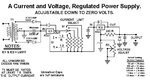
The line that feeds the IC2 Adjust point has originated from only one side of the Center tap transformer output even before the rectifier diode. On its passage to IC2 Adj point, it passes through Diodes, R2. R1 and a 220mf condenser.

I did not find anything like this in any other 317 based circuit. What is its purpose or advantage over other LM 317 based curcuit types?

Could anyone please enlighten me on purpose of that?

Could anyone please suggest me some other circuit to serve my purpose?

Regards-
Debasisswan
 

LM317 specification is that the output is 1.2v higher that the ADJ pin so the minimum voltage in the output is 1.2v.
The circuit that you describe uses a -1.2v fed into the ADJ pin so that the LM317 can have an output down to 0v.
The negative voltage uses a diode and capacitor to rectify the negative voltage and regulates the -1.2v using the resistor R2 and the forward voltage of two diodes (0.6+0.6v) instead of a zener.
If you don't need to have an output lower than 1.2v you don't need that solution.
The circuit also uses the first LM317 connected as a current limiter (you can see that in the datasheet too),
LM317 has a short-circuit protection anyway so if you don't need the current limit don't use that either.

Alex
 

Thanks a lot Alex,
You wrote-

<<<If you don't need to have an output lower than 1.2v you don't need that solution.>>>

In that case, do you mean I can leave the entire connection from CT Transformer one side to Adj. of IC 2 via 220uf Condenser , Diodes, R1 and R? in that case how can I get the voltage regulation at final output? Or if it needs to have reconfigured connection for R2, please explain me how should I do that.

Regards-
Debasisswan
 

Use the TO-3 package devices and put them on a big heat sink. You can find heat sinks already prepared for this size device at many electronic surplus stores.
 
Last edited:

In that case, do you mean I can leave the entire connection from CT Transformer one side to Adj. of IC 2 via 220uf Condenser , Diodes, R1 and R? in that case how can I get the voltage regulation at final output? Or if it needs to have reconfigured connection for R2, please explain me how should I do that.

Just connect the bottom of R1 to GND, as shown on the attached picture ..

IanP
:wink:
 

Attachments

  • Power-Supply-2.JPG
    Power-Supply-2.JPG
    75.5 KB · Views: 105

Thanks KJ6EAD, IANP,

You wrote- "Just connect the bottom of R1 to GND, as shown on the attached picture .." I have seen the picture. Thanks again for your effort to redraw the circuit.

That means, with this change incorporated, the whole circuit will give me a regulated controllable voltage range starting from 16V/12V DC (Depending upon the higher voltage limit of the output of transformer) upto regulated 1.5 V DC in lower side. And it's current output at all voltage setting also will remain adjustable?

Well, if I want to put some Over Charge control in it (As I intend to charge my batteries of different voltage and current capacity with this), can I incorporate some small value resistor~Transistor (BC 548 or similar) based protection with this? If yes, where? at the output of IC2?

I have seen this protector in some circuits and tried to draw it for this diagram with my limited experience and knowledge. But failed to do so. Please help.
Regards-
Debasisswan
 

Hello!!!

I have made a circuit with LM 317, but unfortunately it is not been able to derive a load of about 800 mA. I need to vary the output voltage from 3VDC to 12 VDC and I am giving an input voltage of about 15-16VDC. The circuit is being attached **broken link removed**. With this circuit, my output voltage is varing with the pot at noload, but at load I found that the current being passed is not more than 10mA and the voltage too dropped to 1.5 VDC. Kindly suggest me if any corrections are required.

Thanks!
Surya.

https://obrazki.elektroda.pl/17_1308312724.jpg
**broken link removed**
 

I don't see a problem in your circuit, are you sure that the supply in the input of the regulator can give the output current?
have you tried with a different load that consumes less current, you can try with a 10 ohm 5W resistor for a short while to see the behavior of the output (with 3-5v output for 0.3-0.5A ).
Make sure that you have connected the correct pins of the regulator (ADJ, IN, OUT)

**broken link removed**

Alex
 
Thanks Alex!!!

Thant was really helpful. My connections were, since I didn't go through the pin configuration of LM 317...

Thanks a lot!

Surya.
 

Status
Not open for further replies.

Part and Inventory Search

Welcome to EDABoard.com

Sponsor

Back
Top