Continue to Site

Welcome to EDAboard.com

Welcome to our site! EDAboard.com is an international Electronics Discussion Forum focused on EDA software, circuits, schematics, books, theory, papers, asic, pld, 8051, DSP, Network, RF, Analog Design, PCB, Service Manuals... and a whole lot more! To participate you need to register. Registration is free. Click here to register now.

[SOLVED] PCI16F877 - 4 x 7 Segment LED Counter

Status
Not open for further replies.

WStevens_sa

Member level 2
Joined
Jan 5, 2011
Messages
47
Helped
0
Reputation
0
Reaction score
0
Trophy points
1,286
Location
South Africa
Activity points
1,695
Hi

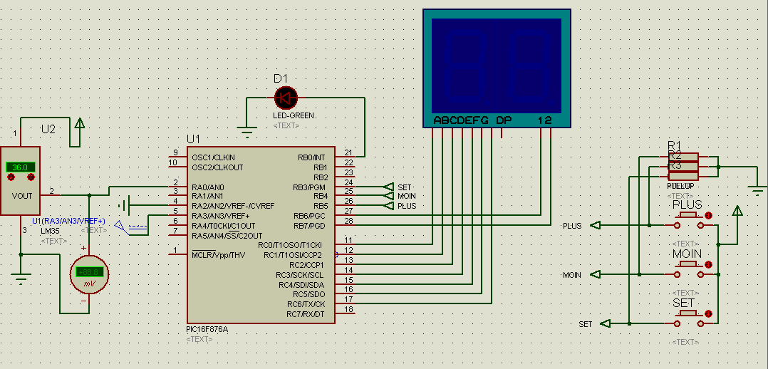
I created the following code from **broken link removed**. 4.11 EXAMPLE 9. I had to convert the code to c. I am sure that I have made a mistake somewhere.

When I simulate it using "real pic simulator" it uses 100% of the MCU and the segments run at such a speed I cannot see what is going on. I have looked through the code so many times and I cannot figure out how to fix it. I know it has something to do with the interrupt trigger time.

Code:
int x = 0;
int digit, portd_index, shifter, number;
int portd_array[4];

void interrupt(void) {

PORTA = 0; // clear porta
PORTD = portd_array [portd_index]; // send correct value to portd
PORTA = shifter;
shifter = shifter << 1;
if (shifter > 8){
shifter = 1;
}
portd_index++;      // Increment portd_index
if (portd_index > 3){
portd_index = 0;      //' Turn on 1st, turn off 4th 7segment display
}
TMR0 = 0;               //' Reset TIMER0 value
T0IF_bit = 0;           //' Clear Timer0 interrupt flag
}

mask(int val){
             switch (val) {
  case 0: return 0x3f; break;   // 0 = 0x3f // 1 = 0x06 // 2 = 0x5B // 3 = 0x4F // 4 = 0x66 // 5 = 0x6D
  case 1: return 0x06; break;   // 6 = 0x7D // 7 = 0x07 // 8 = 0x7F // 9 = 0x6F
  case 2: return 0x5B; break;
  case 3: return 0x4F; break;
  case 4: return 0x66; break;
  case 5: return 0x6D; break;
  case 6: return 0x7D; break;
  case 7: return 0x07; break;
  case 8: return 0x7F; break;
  case 9: return 0x6F; break;
  default:0x3f;
  }
  }

void main()
{
TMR0 = 0;   //Clear timer 0
OPTION_REG = 8;
GIE_bit = 1; //Enable Global Interrupt
T0IF_bit = 0; //clear interrupt flag
T0IE_bit = 1; //Enable TMR0 interrupt
PEIE_bit = 1; //Peripheral Interrupt Enable bit

OPTION_REG = 80;
T0CS_bit = 0; //Internal instruction cycle clock =0
PSA_bit = 0; //Prescaler is assigned to the Timer0

TRISD = 0;   //PORT set to output
PORTA = 0;   //Clear PORTA
TRISA = 0;   //Set PORTA as output
PORTD = 0;   //Clear PORTD
TRISD = 0;   //set PORTD as output

digit = 0;        //' Initial value of variable digit
portd_index = 0;  //' Turn on 1st LED display
shifter = 1;     // ' Initial value of variable shifter
number = 6789;    //' Some initial value on LED display

while(1)
{

digit = number / 1000;         //' Extract thousands //6.789
portd_array[3] = mask(digit);  //' and store it to PORTD array || mask(0xf4) get value from sub function

digit = (number / 100);// mod 10; //' Extract hundreds //67.89
portd_array[2] = mask(digit);  //' and store it to PORTD array

digit = (number / 10); //mod 10;  //' Extract tens //678.90
portd_array[1] = mask(digit);  //' and store it to PORTD array

digit = number ;//mod 10;         //' Extract ones //6789
portd_array[0] = mask(digit);  //' and store it to PORTD array

Delay_ms(1000);                //' One second delay

number++;                      //' Increment number number++;

  if (number > 9999) {      //' Start to count from zero
  number = 0;}
  }
}
 

hi i have some project that i made i hope that help you so
i used just tow 7 degement and i have no problem
i give you here the prog that i manage a controle tempreture and i display it
also with the picture of the circuit
this is the code of th .h file
#include <16F876A.h>
#device adc=8

#FUSES NOWDT //No Watch Dog Timer
#FUSES HS //High speed Osc (> 4mhz)
#FUSES NOPUT //No Power Up Timer
#FUSES NOPROTECT //Code not protected from reading
#FUSES NODEBUG //No Debug mode for ICD
#FUSES NOBROWNOUT //No brownout reset
#FUSES NOLVP //No low voltage prgming, B3(PIC16) or B5(PIC18) used for I/O
#FUSES NOCPD //No EE protection
#FUSES WRT_50% //Lower half of Program Memory is Write Protected

#use delay(clock=8000000)

#define set PIN_B3
#define moin PIN_B4
#define plus PIN_B5
#define une PIN_B7
#define dize PIN_B6


and the .c file
BYTE CONST chif [10]= {0X3f,0X06,0X5b,0X4f,0X66,0X6d,0X7D,0X07,0X7F,0X6F};
// table containe the code of 7 segement
int8 value,un,diz,temp,temp1;

void affiche() // code of the display in 2 7 segments
{

un=value/10; // extract the first right part of the number
diz=value%10; //extract the first left part of the number
output_low(une); //then the out put code by code
output_high(dize); //and of corse one by one for exemple
output_c(chif[diz]); //we turn off the right 7 segment and we display
delay_ms(100); //and we turn on the other
output_low(dize);
output_high(une);
output_c(chif[un]);
delay_ms(100);


}

void main()
{
setup_port_a( AN0_AN1_VSS_VREF );
setup_adc(ADC_CLOCK_INTERNAL);
setup_spi(SPI_SS_DISABLED);
setup_timer_0(RTCC_INTERNAL|RTCC_DIV_1);
setup_timer_1(T1_DISABLED);
setup_timer_2(T2_DISABLED,0,1);
setup_comparator(NC_NC_NC_NC);

// TODO: USER CODE!!
do {
///////////read temp
set_adc_channel( 0 );
value = read_adc();
output_c(value);
affiche();
/////////////testing
if(temp1>value)
output_high(PIN_b0);
else output_low(pin_b0);
///////////////////set temp

if(input(set))
{
do{
start:;
value=temp;
affiche();
if (input(moin)){temp--;goto start;delay_ms(70);while(moin);};
if (input(plus)){temp++;goto start;delay_ms(70);while(plus);};
temp1=temp;
}while(input(set));
}
}while(1);
}


And it is write in ccs compiler


here the circuit


that website is for PIC16F887 not PIC16F877

---------- Post added at 17:39 ---------- Previous post was at 17:34 ----------

**broken link removed**

---------- Post added at 17:43 ---------- Previous post was at 17:39 ----------

https://www.edaboard.com/threads/195119/
https://www.edaboard.com/threads/195090/
https://www.edaboard.com/threads/193534/


I know that. But the 2 MCU's are almost practically the same and quite a bit of code I have written based on 887
 

I know that. But the 2 MCU's are almost practically the same and quite a bit of code I have written based on 887

Hi WStevens_sa!
That example I modified to four 7segment. I Used 16f877,MikroC.
Now it’s working properly.


unsigned short mask(unsigned short num);
unsigned short digit_no,digit1000,digit100, digit10, digit1, digit, i;

void interrupt() {
if (digit_no==0) {
PORTA = 0; // Turn off all displays
PORTD = digit1; // Set mask for displaying ones on PORTD
PORTA = 1; // Turn on display for ones
digit_no = 1;
} else if(digit_no==1){
PORTA = 0; // Turn off all displays
PORTD = digit10; // Set mask for displaying tens on PORTD
PORTA = 2; // Turn on display for tens
digit_no = 2;
} else if(digit_no==2){
PORTA = 0;
PORTD = digit100;
PORTA = 4;
digit_no = 3; // Turn on display for hundreds
} else if(digit_no==3){
PORTA = 0;
PORTD = digit1000;
PORTA = 8; // Turn on display for thousands
digit_no = 0;
}

TMR0 = 0; // Reset counter TMRO
INTCON = 0x20; // Bit T0IF=0, T0IE=1
}

void main() {
OPTION_REG = 0x80; // Set timer TMR0
TMR0 = 0;
INTCON = 0xA0; // Disable interrupt PEIE,INTE,RBIE,T0IE
PORTA = 0; // Turn off all displays
TRISA = 0; // All port A pins are configured as outputs
PORTD = 0; // Turn off all display segments
TRISD = 0; // All port D pins are configured as outputs

do {
for (i = 0; i<=9999; i++) { // Count from 0 to 9999

digit = i % 10u;
digit1 = mask(digit); // Prepare mask for displaying ones
digit = (char)(i / 10u) % 10u;
digit10 = mask(digit);

digit = (char)(i / 100u) % 10u;
digit100 = mask(digit);

digit = (char)(i / 1000u) % 10u;
digit1000 = mask(digit);
Delay_ms(1000);
}
} while (1); // Endless loop
}

unsigned short mask(unsigned short num) {
switch (num) {
case 0 : return 0x3F;
case 1 : return 0x06;
case 2 : return 0x5B;
case 3 : return 0x4F;
case 4 : return 0x66;
case 5 : return 0x6D;
case 6 : return 0x7D;
case 7 : return 0x07;
case 8 : return 0x7F;
case 9 : return 0x6F;
}
}
 
Last edited:
Hi WStevens_sa,

Few bugs were noted in code at first glance;

Always after "digit = number / 1000 , 100, 10" there should be "number=number (mod) 1000, 100, 10" consequently. Otherwise you get 6, 67, 678, 6789 for "digit"; but your requirement is 6, 7, 8, 9.

Also in start of interrupt, always check relevant flag. (there may be several interrupt sources; so we need to identify which one occurred)

Did you calculate how often TMR0 interrupt occur ?

Hope this helps you,
 
  • Like
Reactions: WStevens_sa

    WStevens_sa

    Points: 2
    Helpful Answer Positive Rating
    V

    Points: 2
    Helpful Answer Positive Rating
Hi Denshil
Thanks for your help. It works well only for one thing that I noticed. In my simulator it uses 100% CPU and it counts very slowly. I would like it to count per second. I believe from what I have seen and learned that it is not practical and is a waste to use 877 mcu to run a counter with 4 segmented LED's as it requires major processing power. Logically thinking it would be better to give each segment its own microchip "Not sure which microchip" and the 877 will poll each chip according to the digit required per 1000, 100 , 10 and 1's. This means less load and less ports used on the 877 and makes it available for other functions.

I would like to know from everyone else if this makes sense.

Hi DineshSL
Thank you for noting it. I will do some more reading about "number=number (mod) 1000, 100, 10". I struggled as I had to convert from pic basic to c. I tried to calculate the interrupt trigger time but I just have not figured it out. As mentioned above the fixed code by Denshil which works well still counts to slow and not at a rate of 1 second. I have an idea it has something to do with the interrupt trigger time
 

Yes,
You have internal-instruction-clock source for timer.

To occur timer Interrupt at 1s, find;
Time period for one-instruction-clock cycle;
How may of them are needed for 1 s;
Configure timer to count upto that number.

To get the modulo(mod) in C, some compilers use % operator.
 
Hi WStevens_sa!
You said that this program consuming vast memory.
But Mikroc compiler views another thing.


Hi WStevens_sa!
You said that this program consuming vast memory.
But Mikroc compiler views another thing.


I am using real pic simulator version 1.3 to simulate

---------- Post added at 11:45 ---------- Previous post was at 10:45 ----------

Hi all
I believe from what I have seen and learned that it is not practical and is a waste to use 877 mcu to run a counter with 4 segmented LED's as it requires major processing power This is visible in Real Pic Simulator version 1.3. Logically thinking would it not be better to give each segment its own microchip "Not sure which microchip" and the 877 will poll each chip according to the digit required per 1000, 100 , 10 and 1's. This means less load and less ports used on the 877 and makes it available for other functions.

I would like to know from everyone else if this makes sense.
 

Status
Not open for further replies.

Similar threads

Part and Inventory Search

Welcome to EDABoard.com

Sponsor

Back
Top