Continue to Site

Welcome to EDAboard.com

Welcome to our site! EDAboard.com is an international Electronics Discussion Forum focused on EDA software, circuits, schematics, books, theory, papers, asic, pld, 8051, DSP, Network, RF, Analog Design, PCB, Service Manuals... and a whole lot more! To participate you need to register. Registration is free. Click here to register now.

Signal Detection Audio Switcher Circuit

Status
Not open for further replies.

bwinter88

Newbie level 6
Joined
Jan 11, 2011
Messages
11
Helped
0
Reputation
0
Reaction score
0
Trophy points
1,281
Activity points
1,406
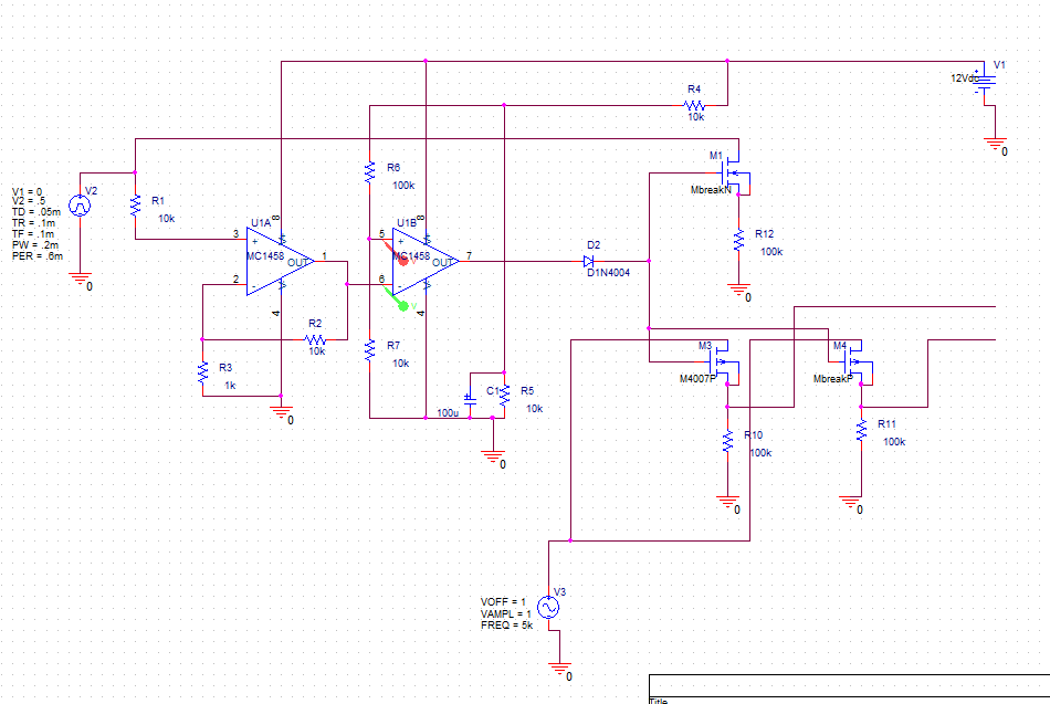
I'm working on a circuit with one output which switches between two inputs. The application is for a car radio; normally, the FM signal goes through to the speaker amp, but when an iPod or attached accessory begins to play, I'd like the output to switch over to that input automatically.

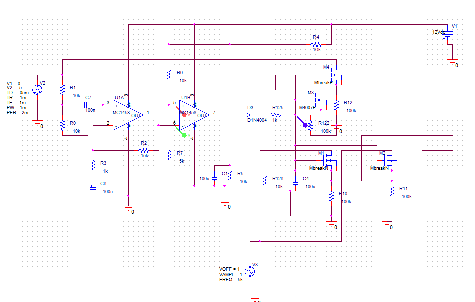
The circuit is based off of a similar circuit used to activate a relay for power (**broken link removed**) instead of using MOS as switches. My understanding is to use a comparator between a small reference voltage and the auxiliary input. When the input goes above the reference voltage, the output is high and instead of a relay, is connected to the gates of two NMOS (L and R of aux input) and two PMOS (L and R of default input). So the NMOS pair turns "on" and the PMOS pair turns "off."

My question is two-fold: 1, can someone take a look at my circuit and see if my thinking is right? I don't like the idea of connecting the PMOS and NMOS outputs together with just a solder dot, can I do that? and 2, I haven't the foggiest idea of what exact model # of transistors to use. My best thought is to look at Digikey and see which transistors they carry the most--assuming that's an indicator of the most popular--but what I'm really looking for is someone to tell me there's a "bread and butter" N- and P-MOS transistor pair that is used for household audio electronics.

Thanks! See circuit below.

 
Last edited:

Alright, I'm really starting to get frustrated with this circuit. Please reference the original circuit in the link I provided (**broken link removed**) for a second.

1) What the heck is R3 doing there? Every time I add it in it bungs up my operation and the comparator won't switch.

2) What the heck is C1 doing there? Adding it causes a DC offset to be added to that op amp input for some reason (~300mV).

In fact, why are there any of those caps there? I could never understand why there were caps before ground, caps before input, on many circuits I've seen and their placement just seemed arbitrary.

3) Why can't I get all the way to 0V with my op amps? They won't go below 1.2V. I thought you could go to 0V with single-rail op amps?

Thanks.


I'm confused. What exactly are you trying to switch? Is it the power supply, the loudspeaker signal or a low level audio signal prior to an amplifier.
The original schematic is just a signal operated relay, it would turn the relay on whenever enough audio was presented at the input jacks and turn it off again after a short break in sound. It was not designed to detect if something was actually present, only if it was producing audio.

Assuming the references are to the original schematic:
1. R8 and R10 form a potential divider to produce half the supply voltage. R3 is there to bias the input of the first amp to that voltage.
2. C1 is to provide DC isolation at the input. It's an AC coupled circuit so if DC reached the first stage it could either stop the relay working or make it permanently close.
3. The 1458 can't swing to the rails, check the data sheet.

The other caps are there:
C2 blocks the DC path so the op-amp can bias itself through R5
C3 ensure there is no signal on the mid-supply line
C4 provides the delay so the relay doesn't chatter in time with your sound, it delays the relay turning off.

Brian.
 
R12 is the component which is clearly wrong as drawn. I can't immediately see where it should be connected.

Perhaps the external audio inputs (the single ended inputs shown as two microphone symbols) needs to be more clearly referenced to the circuit's ground?
I'm surprised that these audio inputs don't also have some adjustable gain (not just to set a switching threshold, but also to normalise the real world possibilities with your actual signal levels).
Also surprising that the rectification is after both amp/comparator stages. I'd expect a full wave rectivier after a single stage of high-gain amplification - but that's not critical.


As betwixt has noted, the circuit doesn't latch. But I disagree that it cannot switch stereo signal sources from 'default' to 'aux input' in the presence of an aux signal. But some fine tuning of signal level around a threshold level will be crucial, and you may be dissatisfied with the switching speed (you could have it jumping between one source and another during brief pauses); attack time is R9 C3, release time is R11 C3.
- - - - - EDIT - - - - -
Component references and circuit comments apply to the circuit in Post 1
The circuit in Post 2 has got absolutely no attack and release time constants - it will chatter on and off with every half cycle of audio!
 
Last edited:

Brian,
Thanks for the help. The clarification on the caps is very helpful. Adding C2 and C1 helped the operation, however adding R3 adds a DC bias which is way too high (0V before the opamp becomes 4V after) and I can't figure out the way to pull it down.

To clarify, I want to use it to switch between two stereo inputs, using two NMOS and two PMOS (one for each L and R input) instead of a mechanical relay. When comparator detects signal, one pair opens, the other closes, and the signal is switched.

DXNewcastle, yea I realized that about the chattering and fixed it by adding an RC pair where it is noted in the original schematic, and it works like a charm. I plan on making the delay about 3 seconds to allow time between songs. However, in reference to attack time and release time, do you mean C4? In terms of adjustable gain, I plan on using trimpots on the feedback resistor as well as R6 so I can adjust the levels. You're right about R12, I just ignored it.

Here's the circuit I have so far. There is still that one issue that bugs me, but...exclude R3, and this circuit works perfectly! (At least in Pspice...)

 
Last edited:

You absolutely must have R3 in circuit, if you omit it the results WILL be unreliable and at best you might get random operation. You have connected the input to the wrong place on the new schematic, it should go to the junction of R0, R1 and C7.

I cannot see what M3 and M4 are supposed to do, it will work the same if you leave them out.

I wonder if you are misunderstanding how the original circuit worked, it was a two stage analog amplifier, rectifier, RC network to provide a time constant and a FET switch driving a relay. Are you trying to change it so it detects a DC voltage at the input point? You also mention comparators but the ICs are used in linear mode, comparators switch in digital mode.

I'm still not sure what is supposed to come out of M1 and M2, does it feed an amplifier or are you trying to directly feed loudspeakers from it?

Brian.
 
You absolutely must have R3 in circuit, if you omit it the results WILL be unreliable and at best you might get random operation.
you're right, and I've edited my design to include R3. Originally I was getting a large DC bias at the output of the first stage but I realized it evens out after a few ms of simulation.
You have connected the input to the wrong place on the new schematic, it should go to the junction of R0, R1 and C7.
So it's wrong in the original design as well? I've only connected one channel, in the actual circuit L and R will go on either side of those resistors, same as the original schematic.

I cannot see what M3 and M4 are supposed to do, it will work the same if you leave them out.
Those are the PMOS transistors being used as switches for the auxiliary input.

I wonder if you are misunderstanding how the original circuit worked, it was a two stage analog amplifier, rectifier, RC network to provide a time constant and a FET switch driving a relay. Are you trying to change it so it detects a DC voltage at the input point?
I added C1 so the first stage is indeed AC-coupled, I'm trying to detect an AC audio signal. Take a look at the circuit again; it's not a two-stage amp, it's a one-stage amp connected to an op-amp in an open-loop configuration being used as a crude comparator. When the output of the first stage goes above the reference voltage on the positive input of the second stage, the second stage outputs the high rail, flipping the gates on the pairs of MOSFETs. I could use a dedicated comparator for that second stage, but I don't need great frequency response, as it just needs to get the basic 'gist' that there is signal.

I ultimately switched out the pairs of MOSFETS for a dual analog SPDT IC.

You also mention comparators but the ICs are used in linear mode, comparators switch in digital mode.
See above, crude comparator, infinite gain, etc. etc.

I'm still not sure what is supposed to come out of M1 and M2, does it feed an amplifier or are you trying to directly feed loudspeakers from it?

Brian.
M1 and M2 are the pair of NMOS transistors being used as switches for the default input to the output. Together with M3 and M4, they comprise the four switches that go between Aux L and R, and Default L and R, to the output.

These are being used to carry line-level signals before an amplifier circuit. No loudspeakers involved.
 
Last edited:

M1 and M2 are the pair of NMOS transistors being used as switches for the default input to the output. Together with M3 and M4, they comprise the four switches that go between Aux L and R, and Default L and R, to the output.

These are being used to carry line-level signals before an amplifier circuit.
I wonder if the confusion here is in the logic of the design?
M1 and M2 switch the default input to the output when the Aux input is silent. [No problem].
M3 and M4 switch the Aux Input to the output when the Aux input is present. [Why switch them? If the Aux is permanently connected then its connected when Aux is audible and connected but silent when its not audible].

In your latest schematic, you have omitted the audio connections from M3 and M4 to the output (and which was correctly shown in your first schematic). This probably adds to the confusion!

I agree that M3 and M4 are not required but their role in connecting the Aux to the Output must be achieved somewhere!
 

[Why switch them? If the Aux is permanently connected then its connected when Aux is audible and connected but silent when its not audible]
I originally had to use them because I thought the output of the comparator went high when an input was detected, but because it's inverting I realized the opposite is true, which does indeed nullify the need for M3 and M4. Regardless, I think we're all on the same page now and I think I finally got the circuit working.
 

heys guys, dose anyone have a final design for this? and has anyone made it? dose it work? cheers people
 

Status
Not open for further replies.

Similar threads

Part and Inventory Search

Welcome to EDABoard.com

Sponsor

Back
Top