Continue to Site

Welcome to EDAboard.com

Welcome to our site! EDAboard.com is an international Electronics Discussion Forum focused on EDA software, circuits, schematics, books, theory, papers, asic, pld, 8051, DSP, Network, RF, Analog Design, PCB, Service Manuals... and a whole lot more! To participate you need to register. Registration is free. Click here to register now.

Seek reliable 12 VDC to 230 VAC 90 watt inverter schematic.

Status
Not open for further replies.

evalon

Member level 1
Joined
May 30, 2010
Messages
34
Helped
0
Reputation
0
Reaction score
0
Trophy points
1,286
Location
Denmark
Activity points
1,592
Hi,

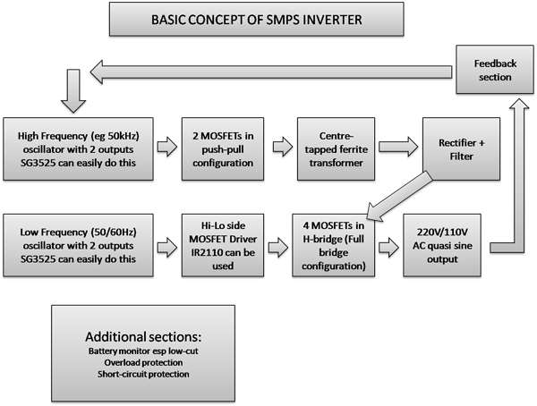
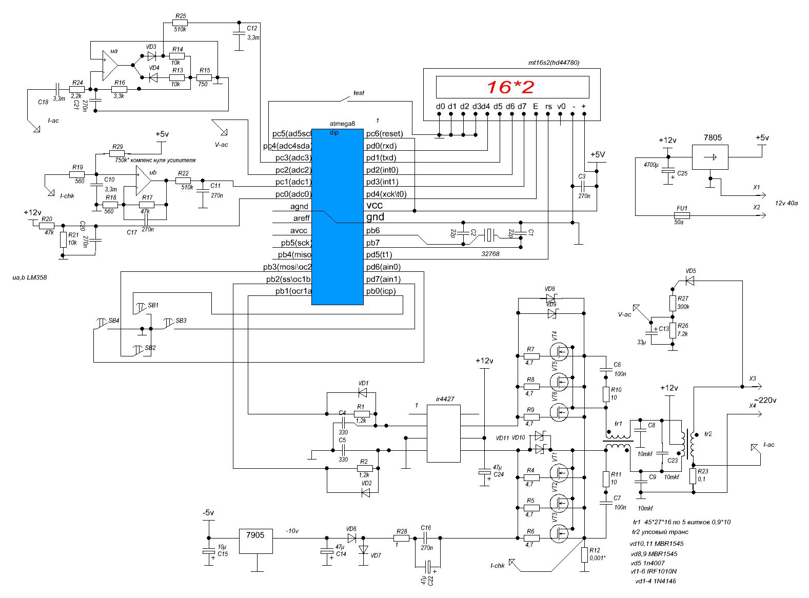
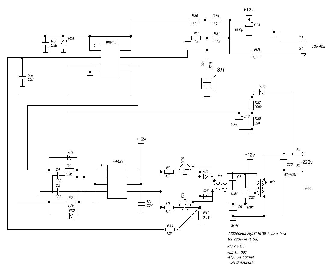
I'm looking for a reliable 12 VDC to 230 VAC inverter schematic capable of delivering 90 watts. Need be low weight, high efficiency and preferably a sinewave inverter or close to a sinewave. Also, I cannot program devices or work with pic's so a simple analog design is preferred.

I have searched the forum but didn't find such a design so hope one of you knows of such a schematic ...

Greetings,

Jesper
 

Well if you dont want to use micro's,then you can only get modified sine output.
 
Hi,
I don't have a complete schematic, but since you want low-weight and high efficiency, SMPS would be a good choice.

Here's an idea:
95_1290961044.png


Check here for some ideas including a posted circuit:https://www.edaboard.com/threads/193437/

Circuit posted in that topic:
51113d1290892317-12v-220v-invertor-sinus-ferit-trafo-nuve-gif


Hope this helps.
Tahmid.

---------- Post added at 23:19 ---------- Previous post was at 23:18 ----------

It's not sine but quasi-sine.

Sine would be best with microcontroller, but here is one without microcontroller, using op-amps.

https://www.wpi.edu/Pubs/E-project/Available/E-project-042507-092653/unrestricted/MQP_D_1_2.pdf

Hope this helps.
Tahmid.
 

Hi Tahmid & kabiru,

- thanks for reading & replying.

@Tahmid: It looks quite impressive the circuitry you have attached :wink: However, it made me realize that what I'm hoping to find is an IC that has everything except for a few external components (like FETs or IGBTs).

Any of you knows of such an IC ( ~12 VDC to 230 VAC at ~90 watts)?

Greetings,

Jesper

you can not get any ic's that can do everthing for you, if the above circute look to complex for you then you will have to build the one with iron core lamination,which does'nt require boost converter,it only uses low freq 50Hz but is not going to be light weight as you expect.
 

Hi,
If you want one IC that does everything, you have to use microcontroller. But if you use a low frequency inverter, it can be done with an SG3525 only, but it's not light-weight. However, if all you want is an inverter, without the protection schemes, the circuit can be simplified, but it's always best to include protection schemes.

Hope this helps.
Tahmid.
 

Hi Tahmid & Kabiru,

@Tahmid: Thanks for suggesting a potentially simpler solution. However, it seems that it may possibly be more complicated to build than I had imagined so I will have to leave it here and opt for buying an inverter.

But I do appreciate the effort you made to help and the suggestions you made ...

Kind regards to you,

Jesper
 

Here the address **broken link removed**
 

Attachments

  • Ups.rar
    161.4 KB · Views: 300
  • OnlyPWM.rar
    77.5 KB · Views: 244
Last edited:

Hi Viknik8 - thanks for posting. As I mentioned in a previous post I now intend to buy an inverter, however, if your suggestion is simple I might be interested.

However, I can't unzip the file to something that I can open. Is it possible that you can post a jpeg file of the schematic?

Best regards,

Jesper
 

Here is a simple inverter circute diagram try it.
 

Here is a simple inverter circute diagram try it.

Hi Kabiru & viknik8

Thanks for following up on my question!

I find your schematics to be very interesting, however, one of my main criteria is - as I wrote in my first post - low weight (as I will be using the inverter on travels) and the transformers in your schematics most likely weigh some :???:

I've found an inverter - a product for sale - which delivers 150 watts in a package that weighs 148 grams 8O . It's something like that I'm hoping to find.

Also, although I may not be using your suggestions I hope they may be of interest to other people as well ...

Greetings to you,

Jesper
 

Hello again,

@Kabiru, if you are still here: The schematic you posted with an 3524 IC do you know if it has been tested so that it works?

Greetings,

Jesper
 

The circute is working perfectly just go ahead and start working on it,but you will need additional circute like low battery protection and overload.
 

Hi Kabiru,

Sounds interesting - I just found that I have a couple of SG3524 ICs and also some PowerFETs, and a 12 VAC/220VAC transformer so I may make it.

Just to prevent any unforeseen challenges if I do: Are there any of the components that need to be a special kind? I'm thinking e.g. of the capacitors and the FET? I don't have the IRFZ44s but instead have IXFX 90N30. Datasheet can be found here:

**broken link removed**

Do you think I can use these instead?

Greetings,

Jesper
 
Last edited:

Hi evalon,
You can use these MOSFET without any problem. The capacitors aren't anything special, just be careful about the voltage rating.

Do you by any chance have any SG3525? If so, the gate driving can be made more efficient without complicating the circuit.

Hope this helps.
Tahmid.
 
The mosfet are ok you can use it.
 
  • Like
Reactions: evalon

    evalon

    Points: 2
    Helpful Answer Positive Rating
Hi Kabiru & Tahmid,

& thanks again for replying. In the first round I have chosen to buy a couple of inverters that are lightweight - I will be using them on a bike and the transformers I have been able to find (as low as 50 watts) have weighed more than a kilo which is too much.

I will, however, have your circuit in mind for potential later use - and then also wonder why nobody appear to have designed (or made available) a circuit where a high-frequency "device" directly synthesizes a 50 Hz sinewave at 220 VAC - sort of like a variable boost converter ...

Be well & thanks again for helping :)

Jesper
 

Hello again,

If you, Kabiru & Tahmid are still watching this thread: I bought a couple of small inverters and have now received them. I took one of them apart and it as far as I remember it is based on two TL494 ICs.

They actually work quite fine - at least with switchmode power-supplies, however, my Weller soldering station doesn't work when powered from the inverter. It lights up but the temperature regulating circuitry does not work. I've tried to insert a vario-trafo between the inverter and the Weller solder station and it might improve things a bit but it essentially still doesn't work.

I really would appreciate a suggestion as to what can be done - preferably in a simple way (AC noise suppression filter or the like...)?

Best regards,

Jesper
 

Hi, i am still here;since your soldering iron does'nt work with the inverter,i dont think using filter's will solve the problem because if you are trying to shape the wave more the more it consume's more current and it can make your mosfet become hot,therefore if you want to use soldering iron use the one that has no electronic control in it.
 

Status
Not open for further replies.

Part and Inventory Search

Welcome to EDABoard.com

Sponsor

Back
Top