Welcome to our site! EDAboard.com is an international Electronics Discussion Forum focused on EDA software, circuits, schematics, books, theory, papers, asic, pld, 8051, DSP, Network, RF, Analog Design, PCB, Service Manuals... and a whole lot more! To participate you need to register. Registration is free. Click here to register now.
I'm designing current sensing circuit for my non-inverting buck boost converter as shown in the diagram.
May I know what amplifier to choose for the circuit? Also how should I design for the current sensing circuit?
You don't show the actual current sense placement. I assume it's meant for the DC output. If in- and output don't share a common ground, the sense resistor may be placed in the negative output, but mostly it's placed at high side. You can use one of the dedicated high side current sense amplifiers available from various vendors. Or use a standard OP with suitable common mode range respectively power supply in a difference amplifier configuration. Many rail-to-rail OPs are able to sense a voltage at their positive supply.
I mean from the DC-DC converter output. I need to sense the output current and display on my PC. However, my output is positive.. The feedback is fed into the inverting input of the op-amp. I need to select a single rail op-amp that the positive output can be fed in. What kind of op-amp should i select? How's the circuit should be?
Hi...
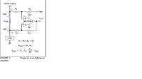
If I'm designing a high side current sensing of single rail as shown in the attached doc. Will it work?
How is the current measured from the circuit and feed into ADC and also what type of resistor should be choosen as the Rsen?
Everything can be calculated from equations given with circuit. For an unipolar current, Vref can be set to zero.
Code:
Vout = Isen * Rsen * R2/R1 (+ Vref)
The dimensioning of Rsen depends on
- the current range
- acceptable Rsen voltage drop
- accuracy requirement
- OP offset and offset drift (offset voltage can be possibly calibrated, offset drift can't)
I have used a circuit like that but connected to the ground side,
the resistors were R1=1K and R2=50K so the gain was 50x ,
my Vref was connected to gnd and the resistor was 0.02 ohm (1%).
so the actual output was 0,02v/A on the resistor and 0.02*50=1V/A in the opamp output.
The values depend on your input and output range as FvM said but in general the Rsen should be
as low as possibles so that you don't create any additional voltage drop but high enough to give an accurate measurement.
Thank guys for ur reply.
I am designing the non-inverting buck-boost converter with input 5V and 2A which gives 10W.
But I require to design an output of 1V and limiting the current to a maximum of 3A. How can it be design?
Regarding the Rsen, is it jus normal resistor will do?
This site uses cookies to help personalise content, tailor your experience and to keep you logged in if you register.
By continuing to use this site, you are consenting to our use of cookies.