Continue to Site

Welcome to EDAboard.com

Welcome to our site! EDAboard.com is an international Electronics Discussion Forum focused on EDA software, circuits, schematics, books, theory, papers, asic, pld, 8051, DSP, Network, RF, Analog Design, PCB, Service Manuals... and a whole lot more! To participate you need to register. Registration is free. Click here to register now.

How to Use the Extra I/O pins in the FPGA Spartan 3 trainer Board ?

Status
Not open for further replies.

blooz

Advanced Member level 2
Joined
Dec 29, 2010
Messages
560
Helped
121
Reputation
242
Reaction score
116
Trophy points
1,343
Location
India
Activity points
4,985
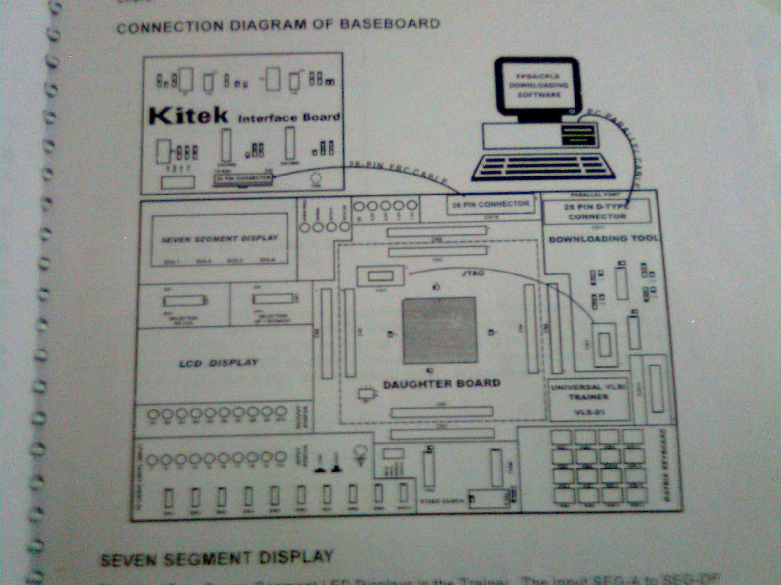
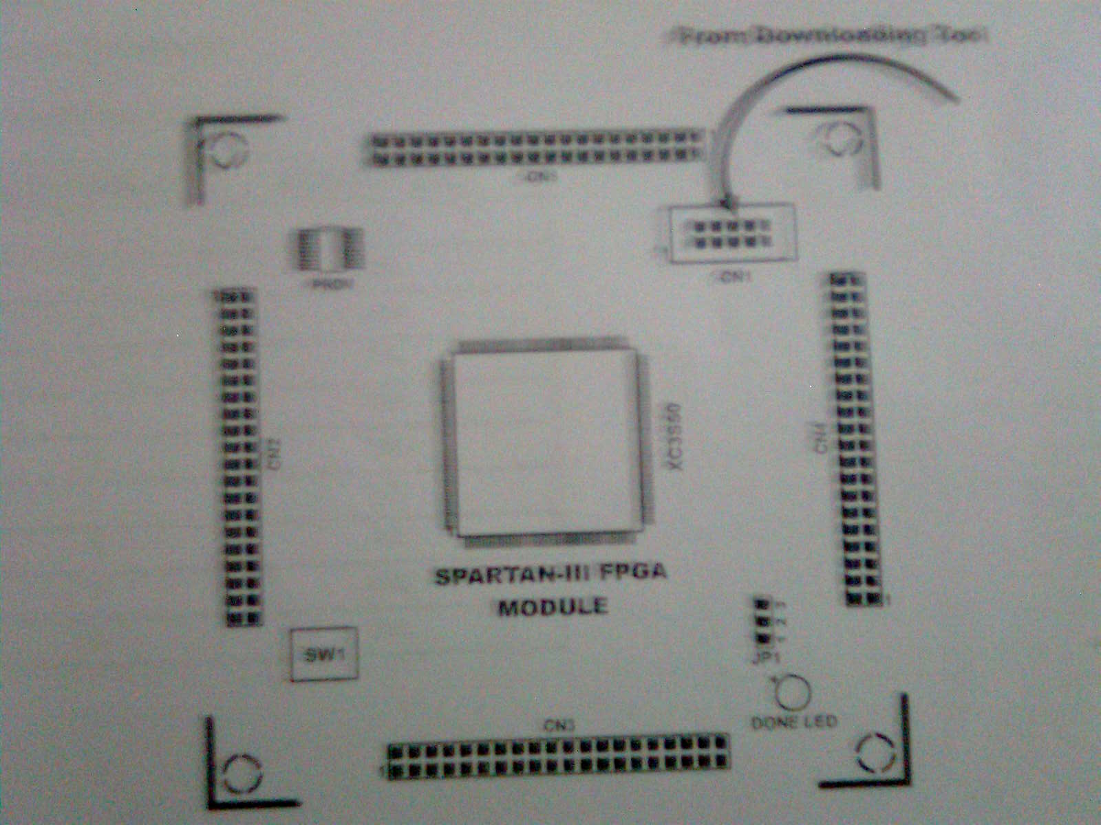
We Want to input more data to our design through the toggle switches provided on the Board ...We have only 10 toggle switch ...How to utilise the unused pins ....There are a set of connectors on the board..How to Use these connectors to interface additional toggle Switches
 

hey,
Which Spartan 3 board actually you are using. Well the empty ports are terminated on the connector provided on board.
To use it you have to extend this connector pins to some general purpose board using its meeting connector and cables. Once these pins available to you, you can connect toggle switches to it. you will find connector details on Spartan 3 board reference manual. or in the reference schematic if you have it.
 
  • Like
Reactions: blooz

    blooz

    Points: 2
    Helpful Answer Positive Rating
hey,
Which Spartan 3 board actually you are using. Well the empty ports are terminated on the connector provided on board.
To use it you have to extend this connector pins to some general purpose board using its meeting connector and cables. Once these pins available to you, you can connect toggle switches to it. you will find connector details on Spartan 3 board reference manual. or in the reference schematic if you have it.

here the diagram of the Kit


the On board FPGA is spartan xc3s400


Is the toggle switch set available in a board as set ...or is it better We make in PCB
 

As I understood FPGA I/O are terminated on connector CN1,CN2,CN3 & CN4. Its a provision to connect daughter card.
What you can do, you can make one daughter card utilizing either one or two opposite connectors depending on your toggle sw requirement and put switches on PCB.
But if you have to put those switches on front panel or something then you have to extend with ribbon cable with meeting connector.
 
  • Like
Reactions: blooz

    blooz

    Points: 2
    Helpful Answer Positive Rating
As I understood FPGA I/O are terminated on connector CN1,CN2,CN3 & CN4. Its a provision to connect daughter card.
What you can do, you can make one daughter card utilizing either one or two opposite connectors depending on your toggle sw requirement and put switches on PCB.
But if you have to put those switches on front panel or something then you have to extend with ribbon cable with meeting connector.

it was really helpful ....thank you
 

Status
Not open for further replies.

Part and Inventory Search

Welcome to EDABoard.com

Sponsor

Back
Top