Continue to Site

Welcome to EDAboard.com

Welcome to our site! EDAboard.com is an international Electronics Discussion Forum focused on EDA software, circuits, schematics, books, theory, papers, asic, pld, 8051, DSP, Network, RF, Analog Design, PCB, Service Manuals... and a whole lot more! To participate you need to register. Registration is free. Click here to register now.

hfss__coupled_microstrip_lines

Status
Not open for further replies.

elektr0

Full Member level 5
Joined
May 2, 2006
Messages
279
Helped
2
Reputation
4
Reaction score
3
Trophy points
1,298
Activity points
3,374
Hallo,

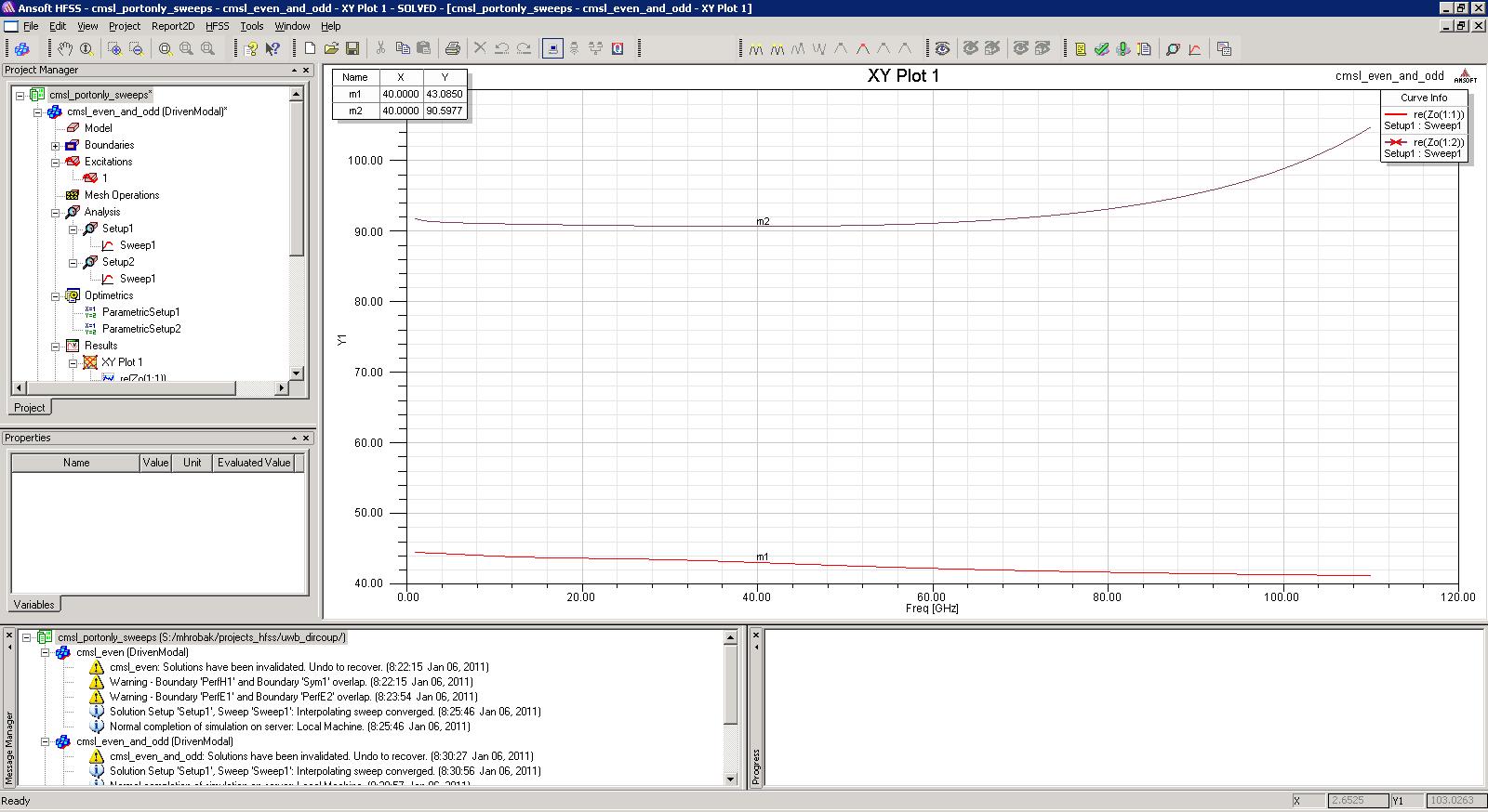
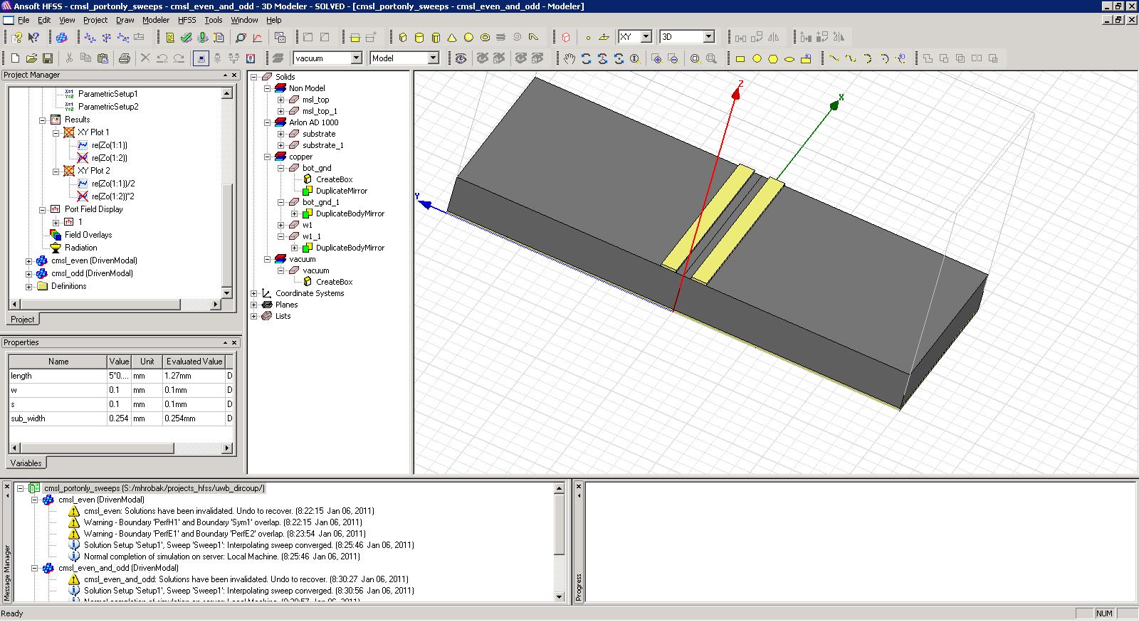
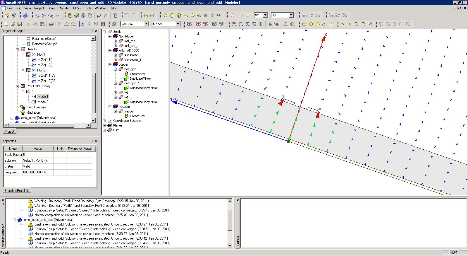
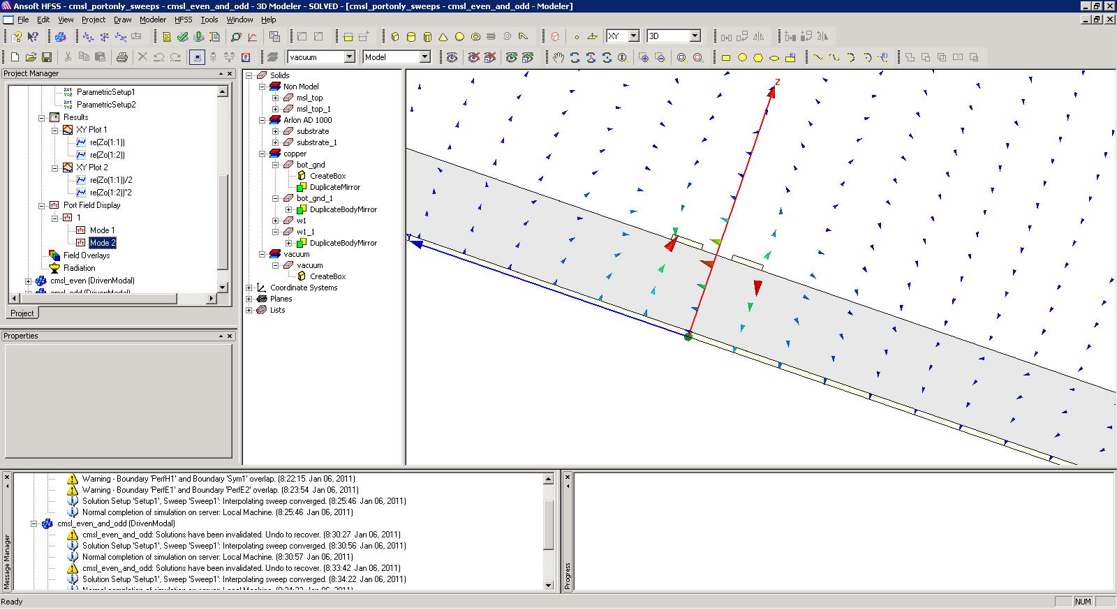
within my port_only_simulation (HFSS) of coupled microstrip lines (2 top strip conductors, bottom ground layer) the even mode impedance is smaller than the odd mode impedance.
Which gives negative k values. k=(Ze-Zo)/(Ze+Zo).

The waveguide port covers the full plane.
Any ideas ?

Thanks for your help.

elektr0
 

you may want to post your project...easier to troubleshoot as it is likely to be a setup issue. Have Fun :)
 

hfss_projects
- waveguide port (2modes)
- half of the structure with pec bound
- half of the structure with pmc bound


added .txt to the hfss project!
 

Attachments

  • cmsl_portonly_sweeps.hfss.txt
    801.6 KB · Views: 98

I looked at your project...you are simulating a Microstrip rather than two coupled microstrips in the model with no symmetry boundary. If you resolve this by making non model (or deleting) the boxes that are shorting your coupled micrtostrips your even and odd modes should be fine.

Also, in your symmetry models there are points to note...when dealing with simulations with multiple modes, rarely does the modes share symmetry as in this case. It makes more sense just to simulate the whole crossection and observe the modes of interest without symmetry. Even when using symmetry, if you are not using the symmetry boundaries, which you are not, you need to set the impedance multiplier to accomodate for the fact that symmetry is being used. Set this by going to HFSS -> Excitations -> Edit Impedance Multiplier. If you are using symmetry boundaries, it will prompt you for both the kind of symmetry and the impedance multiplier. For E symmetry, multiplier is 2...For H symmetry, multiplier is 0.5. If you are curious about the multipliers, there is a short derivation in the help.
 

Hallo tallface65,

I didnt simulate with the microstrip block. I am sorry, I just posted the wrong simulation. Within the pec, pmc boundary simulation, the multipliers were added in postprocessing.
Anyway, the even#1 / odd#2 mode impedance from the whole structure sim does fit with the NOT_MULTIPLIED odd#1 / even#2 mode impedances from the pec/pmc sim.

hmm.
 

Please see the attached photos.
To mee, mode1 is the even mode and mode2 is the odd mode.
Anyway, the calculated impedance values of mode 1 are smaller than the ones of mode2.


I believe the culprit here is that your even mode does not exhibit magnetic symmetry. You can see this a) by the fact that the impedances are not correlating between the full model and the model with Magnetic symmetry, and b) by observing the Electric field vectors of the port field display as you have posted above. If a structure has magnetic symmetry, then the natural Electric field vectors on the plane of symmetry should have ALL E fields as TANGENTIAL to the plane. in your case above, it clearly does not have this characteristic as you have several areas, particularly above the substrate, where the field vectors are not tangential. I would always trust the full transmission line cross section simulation if I have discrepancies between symmetrical models and full models.

have Fun :)
 

Hallo,

let us forget about the symmetry simulations.
The scaling of the port field preview within hfss is not the best. The two pics show even and odd mode, but the corresponding impedances are mixed up.
It would fit, if mode1=odd and mode2=even.
 

I disagree...the fundamental mode of a transmission line cross section is the mode with the lowest impedance. In this case the even mode is the mode with lowest impedance, hence the fundamental mode of this cross section, and the odd mode is the 1st order mode. Due to the more complex nature of the fields (meaning higher energy) of the odd mode, it cannot be the fundamental mode of this cross section (by comparison). Generally, the more complex the field distribution (the higher the Curl of the fields) and the more energy that is needed to maintain the distribution. Higher energy corresponds to a higher order mode.
 

hi. can u send us this project in HFSS . thnx
 

How are the ports (1 and 2) defined ? And are you sure that re(Zo(1,1)) and re(Z(2,1)) gives you even and odd mode impedance? I don't think so.
 

Hallo sv1437,

it is like tallface said and HFSS is right.
The mode which looks like even (mode1) is really the even mode.

The coupling k definition is valid for the normalized even and odd mode impedances, therefore we have to multiply 0.5 to the even and 2 to the odd mode impedance.
This gives k values greater than zero and everything is fine.

If I do the same simulation for different frequencies, it is useful to add an integration line from the left to the right strip to make sure, the port mode numbering doesnt change over frequency.

elektr0
 

Status
Not open for further replies.

Part and Inventory Search

Welcome to EDABoard.com

Sponsor

Back
Top