Welcome to our site! EDAboard.com is an international Electronics Discussion Forum focused on EDA software, circuits, schematics, books, theory, papers, asic, pld, 8051, DSP, Network, RF, Analog Design, PCB, Service Manuals... and a whole lot more! To participate you need to register. Registration is free. Click here to register now.
Hi,
more info are required to answer you.
Anyway a simple guess could be that for some reason you are not performing a frequency sweep analysis ...
Max
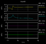
Actually I am doing simulation of LNA on Hspice RF,and seeing results on cosmoscope..but not getting
S-parameters plots correctly as ususally it should be..
I am attaching Spice code for LNA, please rectify my problem...
Thanks..
I am new in RF design and cadence spectre simulation. About the s parameter. what we should expect? In another word, in which range for the s parameter, indicate the LNA is good or bad?
I am learning RF design and that's my first assignment to design and simulate a LNA. I just caculated the parameters for simulation. But the simulation result is quite different from the caculated values. I change the load inductor to make the S11=-3.98dB, S12=-47.54dB, S21=11.737dB, S22=-7.29dB, K=14.65167, NF = 3.734dB.
I am not sure those figure is OK or that's a bad design.
Another thing is I also change the inductor to the Gate (Lg) smaller and I hope to check the input impedance if it is matching but I don't know how to do that in Spectre.
Can anyone give me some help?
This site uses cookies to help personalise content, tailor your experience and to keep you logged in if you register.
By continuing to use this site, you are consenting to our use of cookies.