LNA
Member level 3
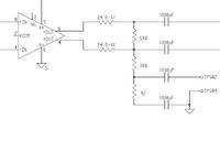
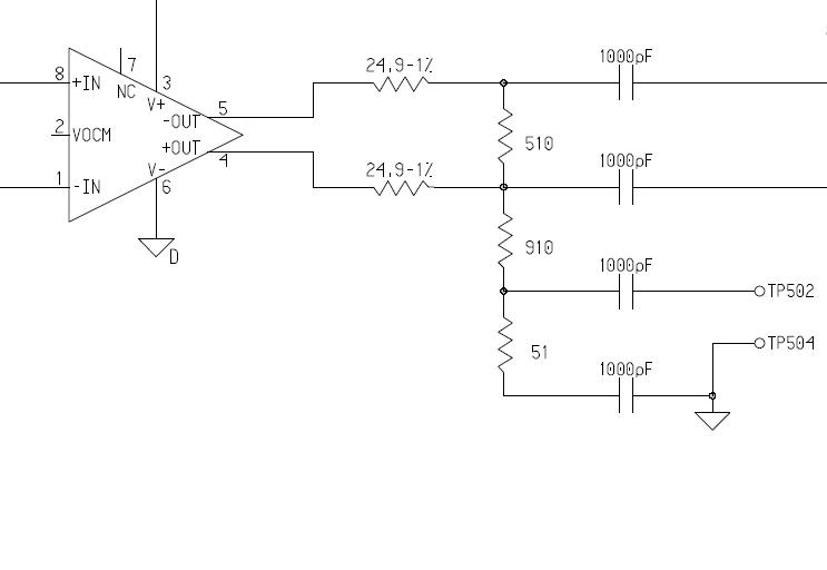
I'm design a test pad circuit to sense IF power coming out a differential driver to ADC. IF is 130MHz. Since the layout limitation balun is not able to used to convert differential to single-ended. A 25dB resistive pad is used to sense the power as attached. A pigtail will be connected between Tp502/504 to sense power.
My questions,
1. How can I calibrate the pad loss?
2. If calibration is not practical, Can I trust the calculated number of insertion loss = 10log ((910+50)/50) = 12.8dB?
3. With this differential driver(AD8131), do I need to take into account common power at the driver output?
My questions,
1. How can I calibrate the pad loss?
2. If calibration is not practical, Can I trust the calculated number of insertion loss = 10log ((910+50)/50) = 12.8dB?
3. With this differential driver(AD8131), do I need to take into account common power at the driver output?
Attachments

Last edited: