Continue to Site

Welcome to EDAboard.com

Welcome to our site! EDAboard.com is an international Electronics Discussion Forum focused on EDA software, circuits, schematics, books, theory, papers, asic, pld, 8051, DSP, Network, RF, Analog Design, PCB, Service Manuals... and a whole lot more! To participate you need to register. Registration is free. Click here to register now.

ism transceiver with better TX channel filtering?

Status
Not open for further replies.

biff44

Advanced Member level 6
Joined
Dec 24, 2004
Messages
5,046
Helped
1,376
Reputation
2,748
Reaction score
1,056
Trophy points
1,393
Location
New England, USA
Activity points
37,902
I am looking for a low cost ISM band (915 Mhz, 2.45 Ghz) transceiver chip with better transmitter spectrum filtering than is commonly available. I have a whole bunch of transmitters running in close proximity, and I want to use the 2nd adjacent channel on a 200 KHz channel plan. For example, while sending data on Channel 50, I want to be able to also use channels 48 and 52 (i.e. 2 x 200 KHz away), even though the "jammer" might be very close in proximity. i.e. I need something that transmitts only in its designated channel, and any extra TX spectrum is tightly filtered out.

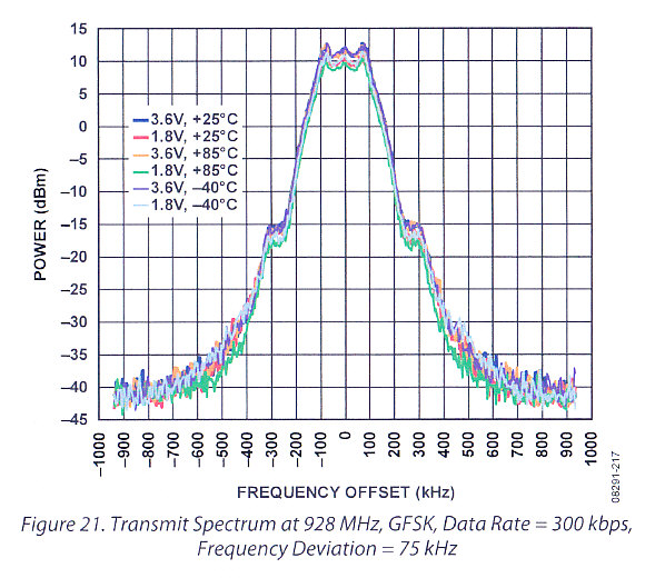
I am using a ~ 70 KHz GFSK deviation, and the RF spectrum is bleading thought to +/- 2 channels away so that I am jamming myself. A CC1101 chip, for instance, is only providing 15-20 dB suppression of the "jammer" 2 channels away (250 kbps data rate, using the smallest deviation and narrowest RX filter I can tolerate).

The problem with this whole class of transceiver chips is that, although many have digital filters in the Receiver, they do not have any filtering in the transmit path. That is, they directly connect the transmitter (a modulated VCO) to the antenna. What I was hoping to find was either a:
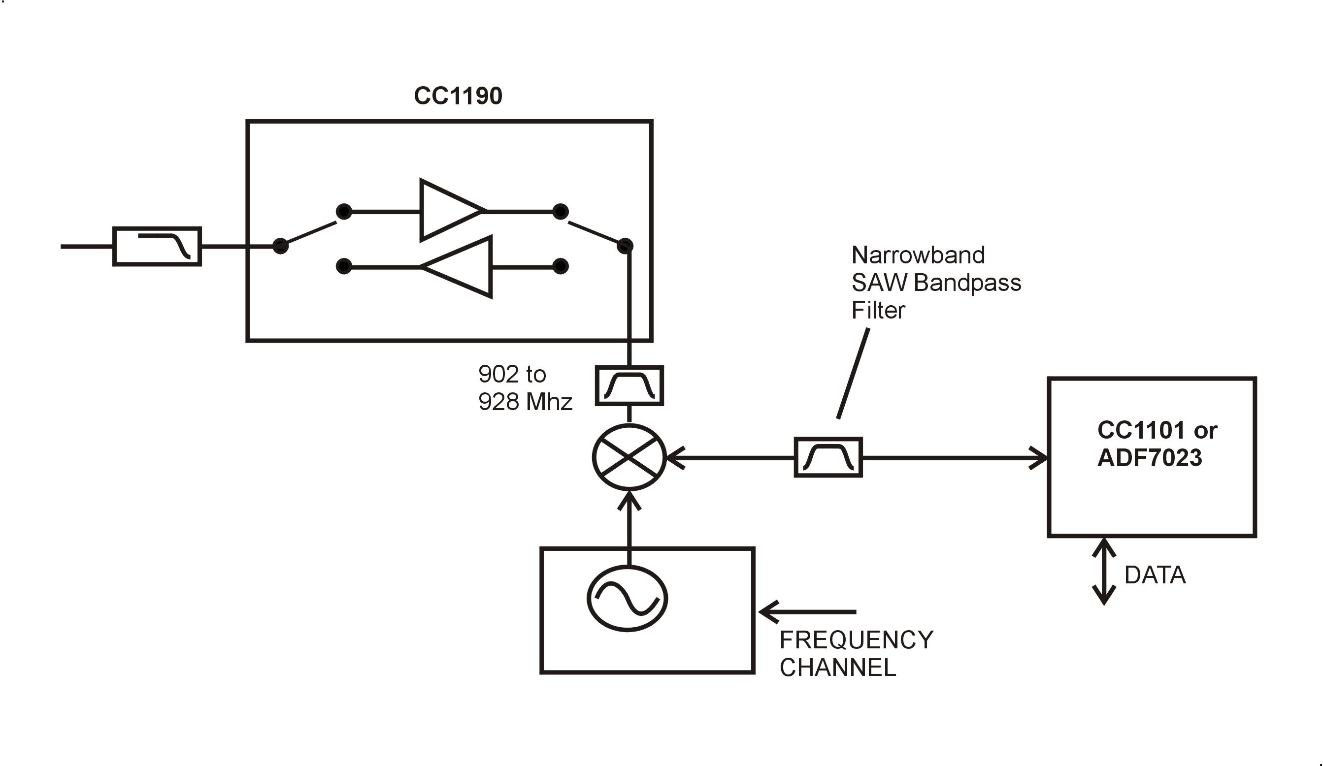
1) Modulator operating at a lower IF frequency, where I can either digitally filter, or apply an external SAW IF filter to it, and then upconvert with a tunable LO to 915 Mhz band.

or

2) Have a completely digital modulation format, where an DAC generates the signal with some digital band-limiting filter, and the chip then upconverts with a tunable LO.

I can not seem to find such a chip/chipset ANYWHERE. Anyone have a suggestion? I have a very tight materials budget, and can not afford to make up the whole block diagram with discrete elements.

I could do the Transceiver at a lower frequency, like 350 Mhz, and up/downconvert, but still need that low cost 315 MHz chip that has tight TX filtering.
 
Last edited:

I didn't yet use the newer Chipcon/TI chips with GFSK, so I can't determine their transmission quality. But it seems pretty obvious, that 250 kbps involves a spectrum widening, that exceeds a 200 kHz channel. So you possibly see just the ideal GFSK spectrum. Did you compare with the theoretical shape? Spurious signals would be another thing, first generation Chipcon devices are known to have some of it due to a bad designed PLL. But they can be clearly distinguished from the regular modulation spectrum.
 

the Chipcon CC1101 I have been testing has the GFSK capabiity, and it does help a little over 2fsk or 4fsk--maybe 10% reduction in occupied bandwidth as eyeballed on a spectrum analyzer. Unfortunately, all GFSK appears to mean to TI is to lowpass filter the analog control voltage going to the VCO tune line. There is no dsp filtering on the TX signal other than that "rounding off" of the corners on the control signal.

And yes, I really have the deviation and RX bandwidths stopped down just to the point that I start getting packet errors. Anything less than an RX Bandwidth of 325 KHz on the CC1101 really makes the packet errors skyrocket. So there is no more help coming there.

I am hoping there is a chip out there somewhere that has much better TX filtering, either by adding a TX IF filter, or by aggressive DSP filtering techinques inside of the chip.

Another approach would be some sort of chipset that employs orthogonal coding, but have not found one of those either. There are DSSS chips, but they don't seem to be set up for this application either--their frequency spreading assures I will be jamming the 2nd adjacent channel. Someone recommended the Atmel RF212 DSSS chip to me, but it needs a 1 Mhz channel spacing, and without orthogonal coding--it does not help me in getting back to my 200 KHz channel plan!
 
Last edited:

Unfortunately, all GFSK appears to mean to TI is to lowpass filter the analog control voltage going to the VCO tune line.
In my understanding, GFSK exactly means filtering of the originally binary FM signal with a Gauss filter. The datasheet doesn't tell about the involved filter, but to deserve the name Gauss filter, it should be at least 2nd order in my opinion. I don't know if it's performing better, but ADI ADF7023 is showing a 300 kbps GFSK spectrum in the datasheet, you should compare to your results.
 

I think that you will hardly find an IC with lower TX bandwidth, for sure using FSK or GFSK. As FVM says, the limitation comes from theory. With this kind of devices you can only reduce the data rate. Modern ICs in ISM band produce Modulated spectrum very close to teoretical one, you can check also Silabs ICs (they acquired Integration associated with its portfolio) such as Si4432.
The idea of adding a SAW to limit the bandwidth, I think does not work. You will cut out useful signal degrading PER.

The solution could be some advanced modulation technique, but no semiconductor company will do this effort for small volume application.

My hint is to check TX spectrum generated by an RF generator with digital modulation capability or use a software package available from analog devices, ADIsimSRD Design Studio.

Good luck.

Mazz
 

You should be able to chop off a few % of bandwidth before your PER goes sky high. A 3% PER is acceptable in this case. I am talking about filtering out the TX to a "~ brick wall" bandwidth of what I am already successfully sending packets thru with the same setting on the RX filter bandwidth, so I know it can be done...I just can not find the chip!
 

I am talking about filtering out the TX to a "~ brick wall" bandwidth
The reason, why GFSK uses a gaussian filter with a soft frequency characteristic is in it's time domain behaviour. A steep ("brick wall") filter would cause considerable time domain distortions respectively bit errors. As long as you don't implement a modulation method involving multi-bit symbol coding, you won't achieve a smaller transmission bandwidth than the said chips have. As I said, I'm not completely sure with the CC1101, but the all digital modulation of ADI chips is very likely at the theoretical limit.

P.S.: I'm not too familiar with communication theory, but I expect, that ideal GFSK is effectively operating at the Shannon rate. This means, you can trade signal bandwidth against signal-to-noise ratio, but not increase both by any filter tricks.
 
Last edited:

FYI in CC1101 modulation is implemented in digital domain.
They have a delta-sigma PLL that allows to have ~100 Hz resolution. In the feedbal loop of the PLL, the fractional 16 or 18 bit word set statically the freq. Using this digital word they dinamically modify the frequency and add a modulation to the VCO. The limit is that it happens inside the loop, so it is low pass filtered (in some sense they have ALWAYS GFSK for high modulation bandwidths).
The advantage is that is very well controlled, so very similar to ideal case (except for spurs, that don't depend on the modulator).
So ADI cannot do much better (wheather on CW phase noise they are much better, but this is not of your interest, I guess).
Just to add a bit of information.

Mazz
 
  • Like
Reactions: FvM

    FvM

    Points: 2
    Helpful Answer Positive Rating
I do not see a whole lot of difference between the TX Spectrum in the ADF7023 data sheet and the measured CC1101 (both at ~300 kbps, 75 KHz deviation, GFSK)

ADF7023:


CC1101:


They must be employing similar GFSK modulation methods. So I wonder if the ADF7023 would have better jammer suppression of 2 x 200KHz away?

BTW, what are those shoulders 25 dB down? Is GFSK non-constant enevelope, and those are 3rd order products in the transmit amplifier? THAT I can do something about!
 
  • Like
Reactions: FvM

    FvM

    Points: 2
    Helpful Answer Positive Rating
Yes, the shoulders are related to IM products.
Also the shape of the shoulders are related to BT product, where B is the 3dB bandwidth of the Gaussian filter and T is the bit duration.
For BT = infinite, the shape of the spectrum is almost as an FSK ( a lot of side lobes), and when BT is minimum (BT < 0.125) the shape is close to an ideal Gauss bell (no side lobs).
 
  • Like
Reactions: tony_lth and FvM

    FvM

    Points: 2
    Helpful Answer Positive Rating

    tony_lth

    Points: 2
    Helpful Answer Positive Rating
here is what I was thinking of trying. Epcos makes a number of narrowband saw filters that can filter out the TX signal, and I can try various bandwidths until I get the packet error rate/jammer suppression balanced:


I was also going to revisit the GFSK vs 2FSK modulation. If 2FSK is more constant-envelope, then I would have less 3rd order spectral regrowth (maybe 2FSK is actually smaller bandwidth for 2nd adjacent channel suppression purposes).
 

Before you build the hardware, you could try a simulation, e.g. with Matlab or Octave.
 

I was also going to revisit the GFSK vs 2FSK modulation. If 2FSK is more constant-envelope, then I would have less 3rd order spectral regrowth (maybe 2FSK is actually smaller bandwidth for 2nd adjacent channel suppression purposes).

Biff

as FvM said the spectral regrowth has nothing to do with modulation sidelobs.
Both FSK and GFSK are constant envelope (infact nonlinear PAs are widely used to have high efficency with this modulations), so don't expect to have lower regrowth with FSK respect to GFSK.

You idea is interesting: be aware of choosing Transceiver freq and external PLL freq to avoid image.

Mazz
 

Hi biff
Have you selected the Transceiver IC among CC1101 and ADf7023?
I wants to develop RF modem based on ADF7023 IC as it provides on board RISC processor for packet level data handling.
If you are working on ADF7023 , kindly suggest me the points to be kept in mind while designing PCb as well as while
developing firmware for it

Regards,
rajan
 

Well, that project is still going on.

Started with a CC1101, and it worked pretty well up to the point that we were testing adjacent channel jammer suppression, and it did not do too well, maybe 16 dB of suppression 430 KHz away.

Played with the ADF7023, and it had slightly better receiver threshold, so I could get better range. And the jammer suppression was a little better too, but oddly it could handle a jammer very well on the high side, but did very poorly on the low side.

Here is test data on the ADF7023:
I set up 3 ADF7023 chips, one as transmitter at 915 MHz, one as receiver at 915 MHz, and one as tunable jammer.

I set them up for 70 KHz deviation gfsk, 200 kbps. I then run the packet error test (4000 packets), figure out the threshold power level, and set up the transmitter to send to the receiver at 10 dB above the threshold level (i.e. with no packet errors).

I then set up the 3rd board as a tunable jammer. I tell it to continuously transmit the preamble (acting a little like a continuous jammer). I then vary the center frequency of the jammer, either above 915 mhz (highside jammer) or below 915 MHz (lowside jammer). I select a jammer frequency, run the PER test transmit to receiver, and increase the jammer power until I see a 5% PER rate.

I get the following data:

HIGHSIDE JAMMER:

Spacing [KHz] Jammer/Signal allowed

430 26.7 dB
514 36.9 dB
535 38.8 dB
639 44.1 dB
800 47.5 dB

LOWSIDE JAMMER:

430 17.5 dB
514 14.8 dB
535 14.5 dB
639 16.3 dB
800 19.0 dB

example: Highside "430 KHz" means the jammer is sending its preamble continuously and is centered at 915.430 MHz, while the transmitter is sending PER test at 915.000 MHz. The jammer is causing a 5% packet error rate when its power is 26.7 dB above the desired signal being transmitted.

What is going on is that the IF frequency is automatically chosen by the RX Filter bandwidth you program in. If you choose a 300 KHz RX filter bandwidth, you get one IF center around 1 MHz. If you choose 200 KHz or lower, you get a lower IF frequency, maybe around 700 MHz.

And, in fact, when I programmed the RX IF to 200 KHz bandwidth, I was finally able to squeek by with something like 32 dB of jammer to signal ratio on the lowside at 639 KHz channel spacing. Unfortunately, for my application (a handheld wireless jammer 1 meter away) I need around 52 dB of jammer/signal tolerance

There are errata sheets on the ADF7023 saying you have to manually program the I/Q phase cal and I/Q amplitude cal for better image rejection, and I played with those registers for a day, but saw no improvement in the above.


BTW, the reason I was on this long search for a chip with good jammer suppression was that I had a large system of wireless units in close proximity, and statistically there was a very high probablility that one handheld wireless transmitter would be sending a packet at the exact same time another handheld was trying to receive a signal from 80 meters away. Normally, if you are sending two way traffic, even if you are on an adjacent channel, your odds of the jammer transmitting his packet right when you are trying to receive your packet are pretty a small probability.

---------- Post added at 21:49 ---------- Previous post was at 21:46 ----------

Biff

as FvM said the spectral regrowth has nothing to do with modulation sidelobs.
Both FSK and GFSK are constant envelope (infact nonlinear PAs are widely used to have high efficency with this modulations), so don't expect to have lower regrowth with FSK respect to GFSK.

You idea is interesting: be aware of choosing Transceiver freq and external PLL freq to avoid image.

Mazz

I too thought that fsk and gfsk was constant envelope, but in gfsk I could see 3rd order products in the spectrum transmitted, and they went down 2:1 in dBs as I backed-off the programmed transmit power. I did not persue it any further, just chalked it up to 3rd order intermods. It might have been something else specific to this chip.
 
Last edited:
  • Like
Reactions: FvM

    FvM

    Points: 2
    Helpful Answer Positive Rating
Two dominate items effect broadband noise floor. The GMSK DAC modulation filter typically only shapes the primary modulation. The ultimate selectivity of the baseband filtering will determine DAC higher frequency attenuation. Second item is sideband noise performance of sythesizer. The best filterless design produces -165 dbC/Hz at 400 kHz offset. This meets GSM spec.

You may be able to find a 800/900 MHz GSM transceiver that will give you what you need.
 

If the target is to immune a a receiver system against jammers, to my knowledge Spread Spectrum is a good choice.
We have implemented FHSS within a military applications wit a special coding technique, obtained pretty good results.
 

Two dominate items effect broadband noise floor. The GMSK DAC modulation filter typically only shapes the primary modulation. The ultimate selectivity of the baseband filtering will determine DAC higher frequency attenuation. Second item is sideband noise performance of sythesizer. The best filterless design produces -165 dbC/Hz at 400 kHz offset. This meets GSM spec.

You may be able to find a 800/900 MHz GSM transceiver that will give you what you need.

Good points. What they DO pack into these tiny chips is truly amazing. I just wish someone would dedicate two pins on the package to IF out and IF in, so that one could add a 1 MHz filter with steep roll off, to augment or replace the internal dsp filtering.

I had not thought about the phase noise of the LO--Normally 2FSK systems can tolerate a boat load of phase noise.....I wonder if I replaced the cheap onboard xtal reference oscillator with one with good phase noise, if my "jammer suppression" would improve?
 

Status
Not open for further replies.

Similar threads

Part and Inventory Search

Welcome to EDABoard.com

Sponsor

Back
Top