Continue to Site

Welcome to EDAboard.com

Welcome to our site! EDAboard.com is an international Electronics Discussion Forum focused on EDA software, circuits, schematics, books, theory, papers, asic, pld, 8051, DSP, Network, RF, Analog Design, PCB, Service Manuals... and a whole lot more! To participate you need to register. Registration is free. Click here to register now.

Simple yet popular interview question coming up lately

Status
Not open for further replies.

rakko

Full Member level 4
Joined
Jun 1, 2001
Messages
233
Helped
10
Reputation
20
Reaction score
6
Trophy points
1,298
Location
mozambic
Activity points
2,065
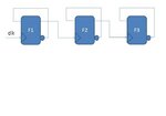
Given this circuit, answer these questions;
1- what is it?
2- How does it work?
3- If clock freq. is increased, which flop fails 1st and why?

my guess is: down ring counter, counts from 7 down to zero and repeats, at high freq., the fastest flop meaning F1 fails 1st..... what do you think.
 

Attachments

  • Presentation1.jpg
    Presentation1.jpg
    14.6 KB · Views: 189

Since the FF's have a single input, they can be either D flip flop or a T flip flop. So the output depends on which type of FF they are. And how can we say which FF fails first?
 

Maybe the schematic did not say specifically, but when you connect the inverted output of the D flop to its input it becomes a toggle flop. Also since each flop output is feeding the successive flop clock input, it makes this circuit a ring counter. As far as how I can tell that it fails as Freq is increased; Each flop has certain setup/hold time constant as well as the external wire delay from Q-NOT to D. If clock period becomes smaller than this constant time, then the flop fails. I say if the period violates the setup time first, then the left flop fails 1st, however, if clock period violated hold time, then the right flop fails. Hope you understand better now.... And no, its definitely not a clock divider.
 

No, this is not a ring counter. The 1st flop toggles every cycle, which gets 1 every 2 cycles. How could it be a ring counter when you have 3 bits and one of the bits gets 1 every 2 cycles ? To be a 3 bit ring counter, each flop should get 1 every 3 cycles.
The correct answer is it's a simple sequential counter that is counting down. This is a typical logic that people use when they implement a clock divided by 2, 4, 8 , etc and it must be a sequential counter.

As for which one fails first when clock speed increased, it's not possible to find the answer without delay information.
Suppose clock is running at 10ns, and the loop of the 1st flop has 4ns delay, and the loop of the 2nd flop has 11ns delay, both passes the timing, but when you increase the clock speed to 5ns, the 2nd flop fails while the 1st flop doesn't.
 
Last edited:

if you're missing hold times any FF could fail. the clock period won't really violate a hold time -- the register has to be able to propagate its output (through inverter) back to its input fast enough to violate its own hold time. changing clock frequency doesn't change the requirement. Its fairly unrealistic to have FF's in an ASIC that have a large enough positive hold time requirement to fail a hold time though. Setup requirements are affected by the increased clock rate, so the FF that changes every cycle will be the first to miss a setup requirement.

I guess "clock prescalar" would be more accurate, but I suspect most people would call it a clock divider. The picture certainly shows the outputs of the registers used for a clock in the next stage, and such output clocks are divided in frequency.

a ring counter is something different than you think. a ring counter counts 1000 0100 0010 0001 1000. This circuit "counts" 000 100 010 110 001 101 011 111 ... Which is a normal counter (FF's in bit-reversed order).

edit -- for the hold times, I mean for this specific example. It's certainly possible to get FF's to miss hold times in other circuits.
 
Last edited:

    V

    Points: 2
    Helpful Answer Positive Rating
my guess is: down ring counter, counts from 7 down to zero and repeats, at high freq., the fastest flop meaning F1 fails 1st..... what do you think.
I agree, except for the "ring counter". It is a ripple counter.
 

As a complete novice at this sort of stuff I'll have a go...

They're all D flip-flops and it counts down from 111 at the first clock cycle. It could be used as a clock divider, the 1st divides the clock by 2 the 2nd by 4 and the 3rd by 8.

The one fed by the original clock signal will fail first if the clock cycle time is less than half the gate setup time... I think

Did I get the job :p
 

if you're missing hold times any FF could fail. the clock period won't really violate a hold time -- the register has to be able to propagate its output (through inverter) back to its input fast enough to violate its own hold time. changing clock frequency doesn't change the requirement. Its fairly unrealistic to have FF's in an ASIC that have a large enough positive hold time requirement to fail a hold time though. Setup requirements are affected by the increased clock rate, so the FF that changes every cycle will be the first to miss a setup requirement.

I guess "clock prescalar" would be more accurate, but I suspect most people would call it a clock divider. The picture certainly shows the outputs of the registers used for a clock in the next stage, and such output clocks are divided in frequency.

a ring counter is something different than you think. a ring counter counts 1000 0100 0010 0001 1000. This circuit "counts" 000 100 010 110 001 101 011 111 ... Which is a normal counter (FF's in bit-reversed order).

edit -- for the hold times, I mean for this specific example. It's certainly possible to get FF's to miss hold times in other circuits.

The series is not exactly the reverse countdown. its 000,100,010,111,000,100,010,111. IF it were to operate as reverse count down there should have been a AND o/p of FF1 and FF2 as the clk to FF3
 

Status
Not open for further replies.

Part and Inventory Search

Welcome to EDABoard.com

Sponsor

Back
Top