Welcome to our site! EDAboard.com is an international Electronics Discussion Forum focused on EDA software, circuits, schematics, books, theory, papers, asic, pld, 8051, DSP, Network, RF, Analog Design, PCB, Service Manuals... and a whole lot more! To participate you need to register. Registration is free. Click here to register now.
I have some confusion about the half bridge converter. Can anyone help me to clarify it? Usually I saw the there are 4 diodes at the beginning of the circuit. What is the difference??
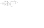
You mean the input rectifier? Your circuit is typically used for 115 V mains voltage. By adding two diodes and a switch, you get a selectable 115/230 V input SMPS, with fixed 300 V bus voltage. It uses a 4-diode bridge rectifier for 230 V and the 2-diode doubler for 115 V. Small SMPS are often wide range 100 - 240 VAC, using a bridge rectifier and a varying bus voltage, but the efficiency is lower than with a fixed bus voltage.
115 VAC is a standard voltage in many countries, I don't think that 110 Vpeak is used anywhere. But I was just describing a typical usage of the circuit. You can use it with any voltage level you like to.
Yes. I'm just trying a certain voltage input. So, this circuit is certainly valid?
For getting the c1 and c2 values, the formula is c1=c2= current/(ripple voltage x frequency). The frequency here is it the input voltage frequency and not mosfet switching frequency?
Since the discharging for C1 and C2 is equal to charging of Cs, (C1xripple voltage1)=(Csxripple voltage). Can it be derived by this way? I can't find a circuit exactly same as this. So I try to derive myself.
This site uses cookies to help personalise content, tailor your experience and to keep you logged in if you register.
By continuing to use this site, you are consenting to our use of cookies.