Continue to Site

Welcome to EDAboard.com

Welcome to our site! EDAboard.com is an international Electronics Discussion Forum focused on EDA software, circuits, schematics, books, theory, papers, asic, pld, 8051, DSP, Network, RF, Analog Design, PCB, Service Manuals... and a whole lot more! To participate you need to register. Registration is free. Click here to register now.

[SOLVED] series pass regulator

Status
Not open for further replies.

obrien135

Full Member level 5
Joined
Nov 10, 2009
Messages
240
Helped
5
Reputation
10
Reaction score
5
Trophy points
1,298
Location
Connecticut
Activity points
3,259
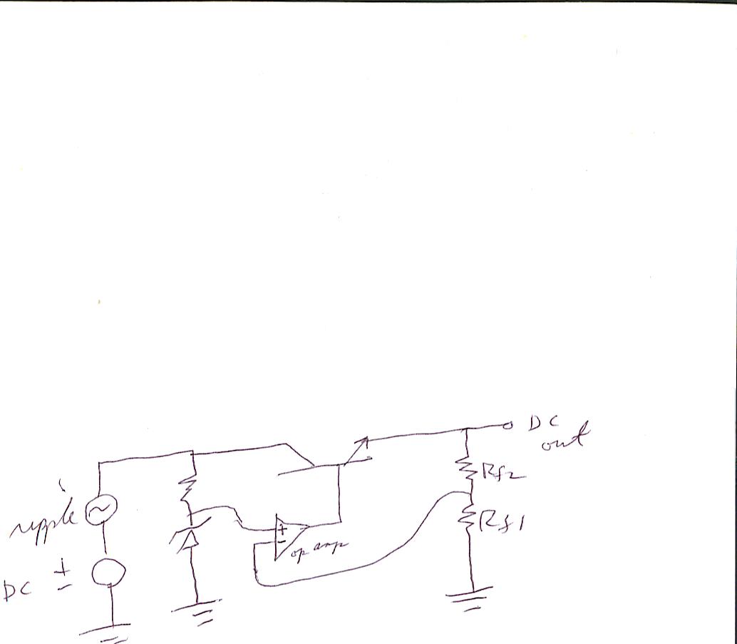
Whan building a series pass regulator, how do you know how much voltage to allow between the collector and the emmitor of the series pass element?
 

It is mainly limited by transistor heatsink capacity, acording device SOA specification ( see datasheet )
 

How do you know when you have ENOUGH input to output differential?
 

Generally 2 conditions:
- vce-sat
- the voltage needed to generate enough base current to have the necessary current for the output.

Post schematic...

Stefaan
 

The following is the circuit that I was going to try:


---------- Post added at 08:30 ---------- Previous post was at 07:58 ----------

I guess , as you said, saturation would be the limiting factor of how much the circuit can prevent the output from dropping with a drop in input. If I allow 2V input/output differential (say 19V in and 17V out) I guess it would work down to an input of17.2V, or maybe not quite that much. If I was using a transformer with a 14VRMS output at 115V on primary and rated at 2 amps and drawing about 1.5A from regulator output, I beleive that would work OK. Would the transforner secondary voltage drop too much at that load? How can I determine this, other than trying it? Transformer cost is a factor to consider.

George
 

Please consider the maximum output of the opamp minus the Vbe of the transistor. The output og the opamp should be considered at a current of Iout/Hfe of the transistor. For example for a Hfe of 40, and 1.5 amp output, this means a base current of 37mA. This is too high for most opamps.

I think if you want to go on this route further, you need a darlington transistor.

Please also consider LM317. It has 1.5 amps current capability, thermal shutdown, current limitation and internal reference. You can normally not destroy it. The LM317 needs about 2V input-output voltage difference for good operation.

**broken link removed**

If you still consider your original idea, put some values/part numbers on your schematic, so it is easier to help you out.

Stefaan
 
Transformer loss occur because 2 reasons :
> CORE LOSS : Use this formula to determine core size --> Ae = 10,000 * SQUARE_ROOT (P) // 60Hz line freq.
> WIRING LOSS : Use AWG table to check proper wiring acording current rating.

+++
 
Status
Not open for further replies.

Part and Inventory Search

Welcome to EDABoard.com

Sponsor

Back
Top