Continue to Site

Welcome to EDAboard.com

Welcome to our site! EDAboard.com is an international Electronics Discussion Forum focused on EDA software, circuits, schematics, books, theory, papers, asic, pld, 8051, DSP, Network, RF, Analog Design, PCB, Service Manuals... and a whole lot more! To participate you need to register. Registration is free. Click here to register now.

[SOLVED] Comment and suggestions of RF amp..

Status
Not open for further replies.

Qube

Member level 5
Joined
Nov 10, 2010
Messages
80
Helped
7
Reputation
14
Reaction score
7
Trophy points
1,288
Activity points
1,896
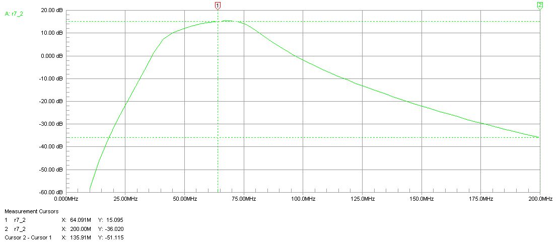
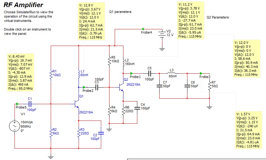
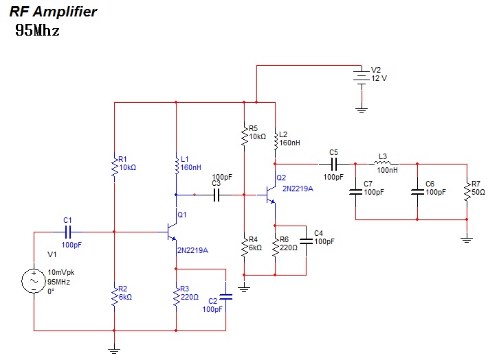
Guys i have made this rough design of RF amp,which can amplify 95Mhz frequency...
Please check it once,and please comment and give me some helpful suggestions..
And also check the Pi filter..
Thank u..
Hope u people will help me to increase my knowledge on RF stuff..

66_1292560899.jpg
 

^^^ sorry typing mistake..
it's actually 95Mhz frequency power amplifier..
 

This is not a power amplifier. There are two low signal amplifiers placed in cascade. The low pass filter at the output has a cut-off at 75 MHz, and need to be re-designed to allow passing 95 MHz signal. (see the attached picture).


This is not a power amplifier. There are two low signal amplifiers placed in cascade. The low pass filter at the output has a cut-off at 75 MHz, and need to be re-designed to allow passing 95 MHz signal. (see the attached picture).


u r absolutely right..
It has limit of 75Mhz..
can u tell me how can i increase it to 95Mhz withould losing the output power..
 

Use any simulation software, you can tune it.
Just change 100nH to 68nH, and change 100pF to 91pF, the the limit is about 95MHz.
 
  • Like
Reactions: Qube

    Qube

    Points: 2
    Helpful Answer Positive Rating
Use any simulation software, you can tune it.
Just change 100nH to 68nH, and change 100pF to 91pF, the the limit is about 95MHz.

please Check out this onee..
I have made it right..
Now the limit is about 115Mhz..
wat do u think....
17_1292647744.jpg
 

For Low Pass Filter use 27pF, 130nH, 27pF. After that to get maximum output power from this circuit (without many changes) increase the value of L2 to 1uH, and decrease the value of R6 to 33 ohms.
 
  • Like
Reactions: Qube

    Qube

    Points: 2
    Helpful Answer Positive Rating
For Low Pass Filter use 27pF, 130nH, 27pF. After that to get maximum output power from this circuit (without many changes) increase the value of L2 to 1uH, and decrease the value of R6 to 33 ohms.
Can u please explain me how u calculated the Low pass filter values as u said..
"For Low Pass Filter use 27pF, 130nH, 27pF"
and also about changing 160nH to 1uH..
It would be a great help if u please explain me how u calculated for this circuit..:smile:


And as per m knowledge,if the value of R6 is reduced tp 33ohms the I(current) will increase and the output power will also increase.please correct me if i am wrong..
 

There are a lot of freeware (or trial) filter design software on the net.

https://101science.com/RFSim99.exe
**broken link removed**

For 3dB cut-off frequency chose a frequency about 20% greater than maximum operating frequency, to do not attenuate the useful signal.
Increasing the current on the last stage increase the power, but also change the output impedance. Ideally is to use a non-linear simulator to get the best output power match.
 
  • Like
Reactions: Qube

    Qube

    Points: 2
    Helpful Answer Positive Rating
Thank u very much Vfone..

From a long time i have a simple doubt but not able to solve it and have no one to help me..
I am able to bias a transistor with Resistors..
But in RF amplifier ,I am not able to choose the inductor value @ the collector of the transistor..

can u please please explain me how u select it value..
Take this schematic as example please..
17_1292647744.jpg
 

The collector inductor of the PA is a choke that sets the collector bias but acts as an open circuit at high frequencies.
In practice the inductance value of the collector choke is not as high as needed for maximum voltage flow. There is a compromise in PA output match design to get both, maximum output power and best efficiency.
 

Status
Not open for further replies.

Similar threads

Part and Inventory Search

Welcome to EDABoard.com

Sponsor

Back
Top