The Lightning Stalker
Newbie level 6
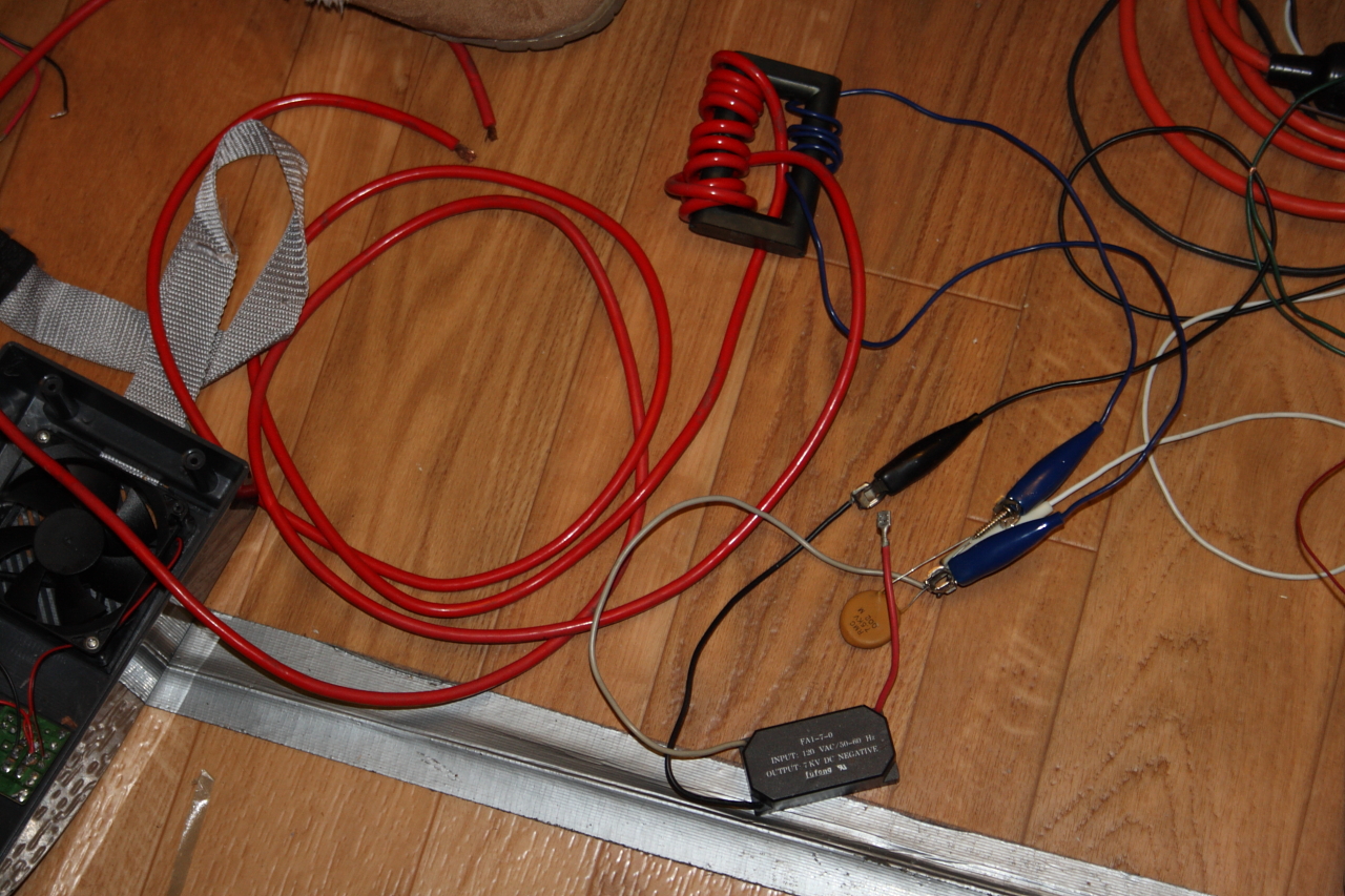
You can see my progress so far in the picture at the end of the post.
It is currently producing some small 3-4mm sparks from the secondary. Does anyone know how to find the resonance frequency of the secondary to get them a bit longer?
The way this works is very similar to a Tesla coil. The capacitor(s) discharge into the primary through a spark gap, just like in a Tesla coil. The secondary is ideally solid bar or heavy wire to carry the welding current. Around 1.5 - 4kV in the primary is stepped up through transformer action, as well as resonance to around 10 - 15kV. This is superimposed onto the welding current to produce a more stable arc for TIG welding, get the arc started without contaminating the tungsten/workpiece, etc.
The ferrite core is from a large television flyback transformer. It's currently being held together with some gorilla glue, so there is zero gap. Some of the mass produced units use a toroid. Others are air core. I was thinking that with the ferrite I could lower the frequency and push more current through.
So any thoughts? It's a simple circuit, but I can produce a schematic if that would help.