Continue to Site

Welcome to EDAboard.com

Welcome to our site! EDAboard.com is an international Electronics Discussion Forum focused on EDA software, circuits, schematics, books, theory, papers, asic, pld, 8051, DSP, Network, RF, Analog Design, PCB, Service Manuals... and a whole lot more! To participate you need to register. Registration is free. Click here to register now.

Need a short beep circuit

Status
Not open for further replies.

Kolero

Member level 1
Joined
Dec 10, 2010
Messages
41
Helped
0
Reputation
0
Reaction score
0
Trophy points
1,286
Location
Vancouver, BC
Activity points
1,795
Hi all

I'm looking for a circuit that is somewhat specific, but I also feel that it's simple to do.. I just can't find a schematic online that does what I want.

I'd like a circuit that uses 555 timer(s) to generate 3 short tones, about 1000 Hz, in fairly quick succession (within about a second) when it receives input from the output of a voltage comparator. It should not not beep again until after the input drops (so I guess it gets reset). I'd also like for it to run on 12v and I have an 8Ω, 0.25w speaker.

And in case that's too confusing, this is what I'm doing:

I have a proximity sensor that has an input of 5v and an output of 0.4-3.1v, depending on how far or near an object is. I have a 12v wall wart, and a LM7805 to feed the 5v to the sensor.
The sensor output is going to a LM393 voltage comparator and when 0.4v is detected, the comparator sends 12v to this new circuit.
This new circuit I'm looking for will beep 3 times quickly then stop. If an object remains in the path of the sensor, it won't beep again until the object is moved and then replaced.

This is for a door sensor. I'll mount it above a door frame and when someone walks in, the circuit beeps. If someone stands under the sensor, I don't want it to keep beeping.
 

To do the timing, I would use a counter driven by an oscillator.

This would be a more elegant and simpler solution than cascading 555s.
 

I was hoping to use the 555s that I have on hand, but I do like the sound of "simpler solution"!

Where might I find such a circuit?
 

I was hoping to use the 555s that I have on hand, but I do like the sound of "simpler solution"!

Where might I find such a circuit?

I suggest that you use a 4017 decade counter.

You could use outputs 1, 3 & 5 to turn on the beep. You would design it to await a start at output 0.

After it is started and has provided the beeps, can be designed to reset at output 6 thus returning it to the original state where it is awaiting a start signal.

The oscillator and tone generator could be 555s or, a CMOS Schmitt Trigger such as the 40106.

The 40106 contains 6 Schmitt triggers. One could be configured as the timing oscillator and another to generate the beep.

I suggest you download the data sheet of the 4017 & 40106(search for either 4017 or CD4017, 40106 or CD40106) and then ask questions if there is something you don't understand.
 
Last edited:
  • Like
Reactions: KJ6EAD

    KJ6EAD

    Points: 2
    Helpful Answer Positive Rating
Okay, so I understand this and how to incorporate it into my circuit:

A person walks under the proximity sensor. The sensor sends 0.5 volts to the voltage comparator. The LM393 voltage comparator, upon receiving 0.4v or higher outputs 12v to the 40106, gate 1. Through a clever combination of a capacitor and a resistor, the 40106 sends a pulsed output of 12v to the 4017 counter. The counter's outputs 1, 3 and 5 connect to the 40106, gate 2. Using a smaller capacitor and varying the resistor for the sound I like, gate 2 outputs to a speaker. Output 6 on the 4017 is connected to the reset. That's sort of a verbal block diagram, but do I have the basics down?

Some questions now:
1) How loud is the output on the 40106? Will I need some sort of amplifier to hear it in a kitchen?
2) Is the 40106 happy with 12v supply?
3) And how can I ensure that the 4017/40106 pair completes the sequence if the sensor stops sending 0.4+v to the comparator?

more about #3.. I got this crazy idea that because the 40106 has multiple gates, I'm not limited to one frequency. I can make a doorbell chime with two or three different notes. I'd have to increase the overall time to play the notes to 2-3 seconds, and by that time a person will have already passed under the sensor. So I'd need the 40106 to continue sending pulses even if the signal from the LM393 stops.
 

I don't have the time to fully answer your questions this evening. I'll respond in detail tomorrow.

However, you're on the right track.

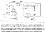
I have attached a circuit I designed for a friend some time ago. It is not what you want, but it will give you an idea of how the 4017 can be used.

Note that gate N1 is a 4093 which is a NAND gate & Schmitt Trigger, so it is used as the oscillator.

The circuit generates any number of pulses from 1 to 9. So, for example, if you press S3, it generates 3 pulses, etc.
 

Attachments

  • Pulse Generator 1.gif
    Pulse Generator 1.gif
    12.3 KB · Views: 223
Last edited:

The answers to your questions: -

1. It should be loud enough without an amplifier, but if necessary, you could use a transistor to increase the level.

2. CMOS devices have a maximum supply voltage of either 15 Volt or 18 Volt - it depends upon the manufacturer.

3. The circuit can be designed so that once triggered, it completes the sequence and then waits for another trigger pulse. How long will the sensor pulse be?

More about 3. Yes it can be designed for multiple frequencies. As I said above, the length of the sensor pulse is irrelevant.
 

3. The circuit can be designed so that once triggered, it completes the sequence and then waits for another trigger pulse. How long will the sensor pulse be?

I'm not entirely sure at this point, until I get a prototype mocked up and hanging above a door. I'm guessing it will be for a second or less.

My local electronics supplier didn't have a 40106 on hand, so I bought a 74HC14 which seems similar, but runs on 6v max. I'm using a LM7805 to supply power to the sensor, so I'll just run all the components off the same 5v to make things easier.
 

The 74HC series is much faster than the 4000 & 74C series, but it should be OK.

The length of the Sensor pulse won't matter as it can be coupled via a capacitor so only the changes will pass through to the counter.

Why does the Sensor only output 0.4 Volt?

Could you post some info on it please? Also the circuit diagram of you comparitor.

Does your supplier stock any of the following:-

74C14, CD4584, MC14585 CD4093? These are all 15 Volt Schmitt Triggers. (the 4093 is a Quad NAND gate Schmitt)
 

For the proximity sensor, I'm using a Sharp GP2Y0A21 Analog Distance Sensor from Pololu - Sharp GP2Y0A21YK0F Analog Distance Sensor 10-80cm (Datasheet is available there as well). It takes 4.5-5.5 volt input, and the output ranges from 0.4 v to 3.1 v depending on the distance from the sensor an object is (32" to 4"). When I have it on my table pointing to the ceiling, it puts out about 0.2 volts or less. I'm expecting that when I mount it above a 7' tall door and when someone 5' tall walks under it, their head will be 24" from the sensor, so it should output 0.5 v. When someone 6' tall walks under it, it should output about 0.9 v. If it's not sensitive enough, I might move it to a horizontal position at about knee-height, but the door is glass and south facing. I'm in western Canada so the doors face the sun and I want to make sure that it doesn't interfere with the IR sensor. Mounting it above the door will shade it from the sun.

The voltage comparator is a LM393 ( http://www.datasheetcatalog.org/datasheets/90/50347_DS.pdf ). The circuit diagram I'm using as here: https://www.edaboard.com/threads/195770/#post820921 with the exception of an added pullup resistor on the output .. but I'm still not sure what value resistor to use. I was going to research that more once I got a pleasing sound for the "alarm" section of the circuit. Right now, as I'm testing the alarm part, I don't have the sensor and comparator connected to it.

I'm not sure if my supplier has the ICs you suggested. They don't have their inventory online, so I can just go in and ask for specific things. When they didn't have the 40106, I asked what they had that was comparable and the 74HC14 was what was suggested, so I bought two. They're cheap enough. I can find out if they have something else if the 74HC14 isn't suitable.
 

I considered using a microcontroller for this task, specifically an Arduino. Partly because I wanted an Arduino to play with, but mostly because I understand software a whole lot more than hardware. But then I also thought that an Arduino would be overkill for this, and I like to challenge myself to learn new things.
 

An Arduino would indeed be overkill. A PIC10F204 could do everything, including the comparator. There are others as well, such as the ATtiny, but I'm partial to the PICs.
 

A PIC10F204 could do everything, including the comparator.
So ... IF I were to go to a PIC10, what do I need? Could I program it with a tune, like the Westminster Quarters?

I'd still like to go with the parts I've already bought for this little project because I seem to just keep buying parts and not using them. Then going back to buy more parts. If I can't get it to work, I'll keep the PIC10 in mind, but I also need to know what all I'd need for it. There must be more to it than just buying an IC, right?
 

So ... IF I were to go to a PIC10, what do I need?
In addition to the chip itself, you would need something to go between it and the computer to program it. There are a lot of programmers out there. You can either build one or buy one. Then just download Microchip's MPLAB IDE software and write the code.

Could I program it with a tune, like the Westminster Quarters?
You're only limited by the amount of memory on the chip.
 

Yes, a PIC would be a simple solution, but if you want to learn more about the hardware, then continue with that.

I'm happy to design the circuit for you if you wish.

For a chimes tune, do you want a gap between the tones? Or should the next tone start immediately?

How many chime tones do you want?
 

Yes, a PIC would be a simple solution, but if you want to learn more about the hardware, then continue with that.
At this point, with all the effort I've put into this circuit as it is, I think I'd like to see it through. I've bought too many parts to just go with one PIC :)

If you're willing to design a circuit, I'd be more than happy to let you!

At the start of this thread, I just wanted 3 short beeps because I thought it was the simplest solution. Now, knowing how easy it is to make different notes with a Schmitt, I like the idea of a tune. The most common tune I can think of is Westminster Quarters, which is a total of 4 notes. But the top of the hour chime is too long, since this is just to alert someone that a customer has walked through the door. It should be noticeable, but short and not annoying. Really, just a Ding Dong doorbell sound would be fine.

While you work on that, I do have a question about it.. Right now I have one gate slowly oscillating, going to the 4017. I have the first 5 outputs on the 4017 going to LEDs, the 6th is empty and the 7th goes to reset. The LEDS light up in sequence nicely. I wanted to send the 6th output to another Schmitt gate to make a tone on the speaker. So the LEDS would go 1...2...3...4...5...(BEEP)...1... etc. Really, just so i could anticipate when the speaker should make a noise.

My question is.. the 74HC14 seems to take a negative input (capacitor from negative to the input). The 4017 sends a positive output. I can't just connect a capacitor from the 4017 to the 74HC14, can I? It doesn't seem right in my head, and it didn't work when I tried it either.
 

At this point, with all the effort I've put into this circuit as it is, I think I'd like to see it through. I've bought too many parts to just go with one PIC :)

If you're willing to design a circuit, I'd be more than happy to let you!

At the start of this thread, I just wanted 3 short beeps because I thought it was the simplest solution. Now, knowing how easy it is to make different notes with a Schmitt, I like the idea of a tune. The most common tune I can think of is Westminster Quarters, which is a total of 4 notes. But the top of the hour chime is too long, since this is just to alert someone that a customer has walked through the door. It should be noticeable, but short and not annoying. Really, just a Ding Dong doorbell sound would be fine. If you only want a Ding/Dong sound, then all you need is a single 74HC14.

While you work on that, I do have a question about it.. Right now I have one gate slowly oscillating, going to the 4017. I have the first 5 outputs on the 4017 going to LEDs, the 6th is empty and the 7th goes to reset. The LEDS light up in sequence nicely. I wanted to send the 6th output to another Schmitt gate to make a tone on the speaker. So the LEDS would go 1...2...3...4...5...(BEEP)...1... etc. Really, just so i could anticipate when the speaker should make a noise.

My question is.. the 74HC14 seems to take a negative input (capacitor from negative to the input). The 4017 sends a positive output. I can't just connect a capacitor from the 4017 to the 74HC14, can I? It doesn't seem right in my head, and it didn't work when I tried it either.

What you're calling "negative" is in fact Gnd or 0 Volt.

You can control the tone by connecting a diode from the Schmitt input to the 4017 output that you want to enable the tone. Connect the cathode of the diode to the 4017 output.

Thus the Schmitt input will be shunted to Gnd while the 4017 is counting through the other inputs, thus preventing the oscillation. When it reaches the output to which the diode is connected, the diode is turned off and the Schmitt can oscillate.

It is a bit more complicated if you want the tone to sound more than once. If you wnat to try that, I explain next time.
 

Thank you for the terminology. I'm used to having positive and negatives on a battery, but is the negative of a battery really 0v or Gnd?

The diode did the trick. So, if I understand this right.. current flows through a diode in one direction only, from the anode to the cathode. Since electricity follows the path of least resistance, the input of the Scmitt has two options: a capacitor or through the diode to Gnd. The capacitor is too much work, so it just flows through the diode.

When the 4017 output reaches the diode, it's sending voltage across which gets stopped by the diode. The current from the Schmitt can't flow through the diode anymore because it is blocked by the positive current at the other end of the diode. Like driving down a one-way alley but now a truck is at the other end. So now the path of least resistance is through the capacitor and the tone is generated.

I don't think I'll need a tone to sound more than once, but I'm fascinated by this, so how would I do it?

Also, if I want to smooth out the tone, to make it less like a square wave, can that be done? Or to extend the last note and fade it out, like a "Ding Donnnngggg..." ?
 

Thank you for the terminology. I'm used to having positive and negatives on a battery, but is the negative of a battery really 0v or Gnd?

It depends on whether you want a positive or negative supply. For a + supply, you connect the Neg side of the battery to Gnd.

For - supply. you connect the + side of the battery to Gnd.


The diode did the trick. So, if I understand this right.. current flows through a diode in one direction only, from the anode to the cathode. Since electricity follows the path of least resistance, the input of the Scmitt has two options: a capacitor or through the diode to Gnd. The capacitor is too much work, so it just flows through the diode. See below.

When the 4017 output reaches the diode, it's sending voltage across which gets stopped by the diode. The current from the Schmitt can't flow through the diode anymore because it is blocked by the positive current at the other end of the diode. Like driving down a one-way alley but now a truck is at the other end. So now the path of least resistance is through the capacitor and the tone is generated.

I don't think I'll need a tone to sound more than once, but I'm fascinated by this, so how would I do it? I'll post a circuit later.

Also, if I want to smooth out the tone, to make it less like a square wave, can that be done? Or to extend the last note and fade it out, like a "Ding Donnnngggg..." ? This is more complicated, so I'll deal with it later.
Yes, the current can only flow from anode to cathode (A to K).

When the 4017 output is low, the K is at 0 Volt. The output of the 74HC is high, so the diode it is biassed in its forward direction. Thus the voltage on the 74HC input is held at about 0.7 Volt. Thus the capacitor charges to this voltage and can't rise further.

When the 4017 steps to the diode, the K is then at the Vcc potential (ie. the K is more positive than the A (remember that the capacitor is charged to about 0.7 Volt so if Vcc = 5 Volt, then there is a 4.3 Volt reverse bias across the diode), therefore the diode is turned off. Thus the oscillator can oscillate.
 

Status
Not open for further replies.

Part and Inventory Search

Welcome to EDABoard.com

Sponsor

Back
Top