Continue to Site

Welcome to EDAboard.com

Welcome to our site! EDAboard.com is an international Electronics Discussion Forum focused on EDA software, circuits, schematics, books, theory, papers, asic, pld, 8051, DSP, Network, RF, Analog Design, PCB, Service Manuals... and a whole lot more! To participate you need to register. Registration is free. Click here to register now.

[SOLVED] PIC18f4550 Oscillator Config help is highly appreciated

Status
Not open for further replies.

signalmo

Newbie level 3
Joined
Nov 6, 2010
Messages
4
Helped
0
Reputation
0
Reaction score
0
Trophy points
1,281
Location
United States of America
Activity points
1,317
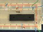
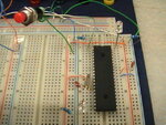
My pic wont' oscillate at all. I believe its the config settings, because It ran good with a test file(.HEX) that I grabbed from this form. It would be nice if we had a small little program for absolute beginners. I have attached the assembly code, the p18f4550.INC file and the pics of the oscillator.Any kind of help will be appreciated.
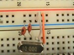
Oscillator type : 10 MH
Caps: 22 pico farads

LIST P=18F4550
#include "P18F4550.INC"
Here is my Assembly code. All I'm trying to do is turn on and of two led's.
Thanks for your time and effort.
~~~~~~~~~~~~~~~~~~~~~~~~~~~~~~~~~~~
CONFIG FOSC= XTPLL_XT
CONFIG WDT=OFF;
CONFIG MCLRE=ON;
CONFIG DEBUG=ON;
CONFIG LVP=OFF;


ORG 0X0000;

Delay1 equ 0XFF
Delay2 equ 0XFF

Start:
CLRF PORTD
CLRF TRISD
; CLRF Delay1
; CLRF Delay2
MainLoop:
clrf TRISD
clrf PORTD
movlw B'11111111'
movwf PORTD

clrf TRISB
clrf PORTB
movlw B'11111111'
movwf PORTB
GOTO Delay
GOTO Delay
; here we turn off the leds


movlw B'00000000'
movwf PORTD


movlw B'00000000'
movwf PORTB
GOTO Delay
GOTO Delay
GOTO Start

Delay:
DECFSZ Delay1,1
GOTO Delay

end
 

Attachments

  • PIC_1493.JPG
    PIC_1493.JPG
    223.7 KB · Views: 99
  • Qstns.7z
    410.2 KB · Views: 83
  • PIC_1499.JPG
    PIC_1499.JPG
    180.9 KB · Views: 93

You connected PIN1 (RESET) to ground.
Chances are the MCU will work once you remove the green/white wire connecting PIN1 to GND and just leave in the resistor.
 

Thanks for such a quick responce. I tried it with resistor directrly connected to pin one. No luck. By the way the green and white wire is a push button switch connected with pin one. I have included a screenshot. Please take a look at it.
 

Attachments

  • PIC_1495.JPG
    PIC_1495.JPG
    226.1 KB · Views: 100

I haven't done any PIC programming for a few months now, so I might be wrong - but you've assigned two constants (255) as Delay1 and Delay2, but you're trying to decrement them as if they were registers.
I think what you need to do is use one of the existing General Purpose Registers (They start at 0x20 if I remember correctly) and assign a 0xFF value to them by doing:

Delay1 equ 0x20
Delay2 equ 0x21

and later in code instead of CLRF Delay1....

MOVLW 0xFF ; literal 255 to Working reg
MOVWF Delay1 ; Working reg to Delay1 (GPR at 0x20)
MOVWF Delay2 ; Working reg to Delay2 (GPR at 0x21)
 

Once again thanks for your help.
I tried it with Delay1 equ 0X20.
Still no luck . May be I have to set some values for post scaler and prescalers.
Here is the my code. The changes are highlighted by ~~~~~~~.


LIST P=18F4550
#include "P18F4550.INC"

CONFIG FOSC= XTPLL_XT
CONFIG WDT=OFF;
CONFIG MCLRE=ON;
CONFIG DEBUG=ON;
CONFIG LVP=OFF;


ORG 0X0000;

Delay1 equ 0X20

Start:
CLRF PORTD
CLRF TRISD

movlw 0XFF
movwf Delay1 ; initilizing counter ~~~~~

MainLoop:
clrf TRISD
clrf PORTD
movlw B'11111111'
movwf PORTD

clrf TRISB
clrf PORTB
movlw B'11111111'
movwf PORTB
GOTO Delay
GOTO Delay
; here we turn off the leds


movlw B'00000000'
movwf PORTD


movlw B'00000000'
movwf PORTB
GOTO Delay
GOTO Delay
GOTO Start

Delay:
DECFSZ Delay1,1
GOTO Delay

end
 

Ah, another small thing - the delay subroutine:

Here's what it does:

Decrement Delay1, skip next instruction if zero.

So, it makes 255 loops until it decrements Delay1 to zero and then reaches 'end'. What you probably want to have there is 'RETURN' just after GOTO Delay.
 

Your delay routine only counts down from 255 to 0.
Your clock is 48 MHz (multiplied with a PLL from external crystal) which gives a rate of 12.000.000 instructions per second. The delay only does 255 instructions which is a lot less than 1 milisecond.

So, even if it's working - you wouldn't see the LED blink because it bliks over 1000 times a second and you can't even see it.
 

Status
Not open for further replies.

Similar threads

Part and Inventory Search

Welcome to EDABoard.com

Sponsor

Back
Top