Continue to Site

Welcome to EDAboard.com

Welcome to our site! EDAboard.com is an international Electronics Discussion Forum focused on EDA software, circuits, schematics, books, theory, papers, asic, pld, 8051, DSP, Network, RF, Analog Design, PCB, Service Manuals... and a whole lot more! To participate you need to register. Registration is free. Click here to register now.

clean FFT for Class-D simulation

Status
Not open for further replies.

ansu_s

Junior Member level 3
Joined
Nov 8, 2008
Messages
29
Helped
5
Reputation
10
Reaction score
4
Trophy points
1,283
Activity points
1,610
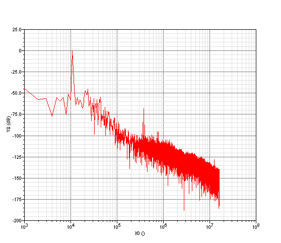
Hi, how to get a clean FFT in Class-D simulation? I start from ideal model and want to slowly build in non-idealities and see the effect on Class-D performance. So with simple 384khz PWM Class-D with third order output filter, I aim for aliasing below -100dB (so can see all distortions greater than this), and so need 46.6x oversampling. So I use 20MHz FFT sample frequency (50ns sample spacing). But this is what I get in spectre sim:


Not great, for ideal PWM! Why the -50dB noise floor? I try increasing reltol setting (from 1e-3 to 1e-6) and this helps a small bit, maybe now -65dB. Big help is reducing strobeperiod from 50ns to eg. 0.5ns, which gets -100dB but with very, very long simulation time! Anyone has tips on how to get clean FFT with OK runtimes?
 

try decreasing maxstep. I don't think improving reltol would be that useful. By the way, why 46.6 times oversampling?
 

It seems that you are correctly using coherent sampling in your simulation. I agree with amriths04 that you need to play with the simulations parameters, starting from maxstep: the simulator sees a slowly changing signal and will make big steps, your FFT is interpolating between simulation points and therefore shows higher noise. Try maxstep=25ns...
 

46.6x oversampling because want 100db attenuation of switching harmonic. Using 3rd order class-D output filter (60dB/dec), so -100dB is at 17.81MHz == 46.6 * 384khz.

maxstep=25ns gives -60db noise floor. I think that strobeperiod is the same as maxstep? maxstep sets max simulation step, strobeperiod sets how often simulator needs to write datapoint (and to write datapoint, it needs to compute signal value at that step). Doesn't seem an easy (short sim time) way of getting clean FFT's in Class-D then.
 

strobeperiod is a better option if you are only interested to see the strobed points (the simulation will not run faster though!).
I am not sure how you calculated 60dB for 25ns but I believe you got the point: this type of simulation will take a long time.
 

what's the cut off of you 3 rd order filter?
strobeperiod does not have anything to do with simulation accuracy. However, maxstep has. By decreasing maxstep, you are forcing the simulator to solve the equations more often (even though it might not be required because of lack of transitions).
In this case, you must first determine how much pulse width error you can tolerate to get the required snr and set the maxstep accordingly.
It is a known that if the pulse widths are exactly ideal it must have no distortion components. However, you have to ensure no intermodulation components fall into your in-band.
 

Status
Not open for further replies.

Part and Inventory Search

Welcome to EDABoard.com

Sponsor

Back
Top