Sajjadkhan
Full Member level 5
- Joined
- Sep 25, 2010
- Messages
- 307
- Helped
- 17
- Reputation
- 34
- Reaction score
- 16
- Trophy points
- 1,298
- Location
- Rawalpindi,Pakistan
- Activity points
- 4,199
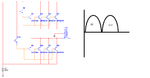
I have to make Pure Sine wave inverter. I almost completed it but there are few serious problems. so help. Diagram is attached giving the idea how i connected the circuit.
I have used Bubba to produce 50Hz sine wave(DONE).
I would be using Class B amplifiers (2n3055)
for that i have to rectify the signal and which is done.the first pulse is fed to transistor Q5 and the same pulse with 180 degree phase shift is fed to Q10.
The transformer windings are as follow
****************
Secondary Turns----Voltage
20+20-----------------12+12
*****************
Primary Turns-------Voltage
324-------------------180
360-------------------200
390-------------------220
432-------------------240
468-------------------260
****************
The input signal to the transformer pin 2 and 4 are of 18v(12.7v RMS) and the out put is of 224v(158V RMS) and this 224 volts are on the 468 turns. why such a low voltage i m receiving at the out put. which should be 421V(298V RMS).
Why is that?
clue:Yes one thing i have noticed that when i remove one pulse and observed it for a single pulse then the output goes to near 421v peak (half wave rectified) but as i connect the other input then i get full sine wave with too much attenuation.
I dont get it why its happening?
2nd while having the sine wave at the output with No Load the input current must be in milli amps because of the Back EMF. but still it draws 17 Amps of current at input side.??????????
PLZ help.
I know the other method is class D amplifiers that is PWM tech but that is out of my scope. so i have to do this. and i m left with a month and a half so plz help.