Continue to Site

Welcome to EDAboard.com

Welcome to our site! EDAboard.com is an international Electronics Discussion Forum focused on EDA software, circuits, schematics, books, theory, papers, asic, pld, 8051, DSP, Network, RF, Analog Design, PCB, Service Manuals... and a whole lot more! To participate you need to register. Registration is free. Click here to register now.

BandGap Comparison Question..... please help.................

Status
Not open for further replies.

gilbertomaldito

Full Member level 3
Joined
Aug 21, 2006
Messages
159
Helped
4
Reputation
8
Reaction score
3
Trophy points
1,298
Activity points
2,385
Hi

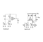
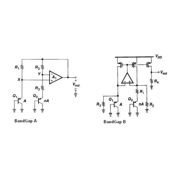
Attached are two simple types of bandgaps. I just want to ask what is the problem with bandgap A why books have to come up with bandgap B?
I know as I read the books that bandgap A has problems with the opamp's offset and resistors dependency on temperature, but I just dont understand how bandgap B solve bandgap A's problems?


Thanks

Andrew
 

Attachments

  • Bandgapsj.JPG
    Bandgapsj.JPG
    19.8 KB · Views: 104

In bandgap, the PTAT current is obtained by the delta_Vbe/R circuit. The implicit assumption is that the same current flows through both transistors!
In Bandgap A, the opamp offset and mismatch will contribute to the current difference.
In Bandgap B, if we ignore R2/R3 for the time being, the current difference depends only on the opamp offset multiplied by lambda, the channel length modulation factor. This is much superior to Bandgap A. R2/R3 is probably used to compensate the offset of the opamp via trimming. They will result in deviations in the PTAT current, but may lead to a better overall performance.
 

for B:Vout=R4*[Vbe/R3+VT(lnn)/R1]
there is no have res temp but also have amp offset
 

The advantages of Bandgap B is the possibility to adjust the value of the output voltage when
VREF = R4 * [ VBE1/R3 + deltaVBE/R1 ]. You can configure the ratio R4 in order to achieve the desired value of output reference. As a consequence, BGR B can operate with VDD less than 1.0 volts. It is the classical Banba architecture for bandgap with low-voltage operation.
BGR B requires VDD higher than 1.2, and does not permit adjustment of the output voltage. This is the major difference between these two approaches.
In my option, both circuits are able to be trimmed.
There is a difference regarding the mismatch current. In BGR A, it depends on the matching of two resistor (and offset, BJT mismatch, etc) , while BGR B depends on the matching of the current source (MOSFET).

Regards,
 

Status
Not open for further replies.

Part and Inventory Search

Welcome to EDABoard.com

Sponsor

Back
Top