Continue to Site

Welcome to EDAboard.com

Welcome to our site! EDAboard.com is an international Electronics Discussion Forum focused on EDA software, circuits, schematics, books, theory, papers, asic, pld, 8051, DSP, Network, RF, Analog Design, PCB, Service Manuals... and a whole lot more! To participate you need to register. Registration is free. Click here to register now.

[SOLVED] Problem with a circuit. - long tailed pair

Status
Not open for further replies.

zia.newversion

Member level 5
Joined
Mar 28, 2010
Messages
83
Helped
1
Reputation
2
Reaction score
1
Trophy points
1,288
Location
Pakistan
Activity points
2,188
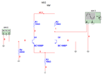
I am not very good at electronics. In my Analog and Digital Electronics Lab last week, I performed a task. The teacher displayed a circuit diagram and gave a brief lecture on the specific type of amplifier... Incidentally, I did not take notes except copying the diagram... I was trying to simulate the same diagram on Multisim today but I am consistently failing to receive an amplified output. The circuit diagram (screenshot from Multisim) and the sim file is enclosed.
Please tell me what silly mistake I am making. I shall be really thankful. :)

EDIT: I think it is called a "Differential Amplifier"... I have taken the basic electronics course but I am not familiar with this type of amplifier. At first i thought it was a Darlington pair, but then I remembered that D-Pair is two BJTs connected emitter to base... Anyway, I am totally blank on this specific circuit. Some theoretical comments will be helpful.

DISCLAIMER: I am not posting this thread because I have an assignment or a test due... I am asking for your help because I am suddenly very interested in this specific problem.
 

Attachments

  • sim.rar
    49.5 KB · Views: 114
  • asg1.png
    asg1.png
    20.2 KB · Views: 211
Last edited:

I don't have multisim, so I can't check your circuit. But from what I can see, your transistors have no DC bias. Check if you have given Ac signal (Which I can see you have) at the input, but it should also have a DC offset. This DC offset is required to make the transistors go into saturation. A BJT would require 0.7V for this.

Hope that helps.
 

Shravan,

I think you are right about the lack of DC to turn on the transistors, however, you don't want them in saturation - I think you are thinking of MOSFETs.

Keith

PS. Actually I have just noticed there is 5V on the base of Q1 in which case you need to put 5V to the base of Q2 (unless they are node names not voltages!)

Keith
 
Shravan,

PS. Actually I have just noticed there is 5V on the base of Q1 in which case you need to put 5V to the base of Q2 (unless they are node names not voltages!)

Keith

I didn't quite get it. There is an AC signal on the base of Q1 (20mVp)... And Q1 and Q2 are transistors...
Let me tell you what I get on the oscilloscope. I get a constant DC equal to Vcc... Which might mean that the circuit is open at Q2, or there is no current going through Q2... Which is weird... As far as I know, all of the current goes through Collector to Emitter with a little current going through to Base... At least that is my basic understanding of BJT...
So, what would I do with the circuit? I am gonna give a C offset of 1V to my AC signal as Shravan pointed out... Maybe that works...! :)

EDIT: No that doesn't work. :(
 
Last edited:

Yes, you need to have a DC voltage to turn the transistors on. One way is to connect the end of R3 to a negative voltage instead of ground. The other way is to apply a DC voltage to BOTH transistor bases. The first link posted by alexan_e shows another option.

Keith.
 
Yes, you need to have a DC voltage to turn the transistors on. One way is to connect the end of R3 to a negative voltage instead of ground. The other way is to apply a DC voltage to BOTH transistor bases. The first link posted by alexan_e shows another option.

Keith.

Oh K!!! I got it... Thanks a lot. Silly me, I put a ground where actually I should have put a -Vcc... Thanks a lot for pointing out... It is giving an output now.
But strangely, the output is equal to the input. 0dB gain! Why's that? Why isn't it amplifying?

EDIT: Rather it is attenuating... I have a 20mVp signal at input and I am getting about 15mVp signal at output. :\
 

It should be giving you some gain. What voltage have you used for -Vcc? Check the collector & emitter voltages - it should give a clue as to what is wrong.

Keith.
 

It should be giving you some gain. What voltage have you used for -Vcc? Check the collector & emitter voltages - it should give a clue as to what is wrong.

Keith.

Used -10V for -Vcc...
Checked the VC and VE... Both are around -720mV for both Q1 and Q2... And I have absolutely no idea what that means! :\
And I shall be really glad if you keep elaborating a little from theory point of view in addition to giving practical tips. :)

(Sorry if that sounds like I want you to act as my professor, :p. But I really have no other option)
 

The emitters should be -720mV but the collectors should be around 5V, I think. Have you changed the resistors or the collector supply?

Keith

---------- Post added at 20:49 ---------- Previous post was at 20:46 ----------

By the way, for some theory have a read of the links posted earlier.

Keith
 

Thanks a lot Keith. I owe you so much... :)
Great! I have spent quite a lot of time on this problem, I guess I should go to bed right now. I shall experiment a little more on this tomorrow and post here again if I still am that dumb after a sound 10h sleep! :)
By th way, one last thing. What did you use to simulate and generate that pdf for me? I might not be that much into electronics but I am way into software. ;) So, could you please let me know about th software? Maybe I'll give it a try, just for fun. :) The frequency plot was cool, and I don't think Multisim could do that...
Thanks a lot once again and have a really nice time. :)
 

almost any circuit simulator can do that, it is called AC analysis, you select an ac source in the input
of a circuit and measure the frequency response (gain/frequency graph).
Multisim can do that , instead on doing an interactive simulation you have to open the simulate menu and you will find a sub-menu (analysis) in which you can find many types of analysis.
The most useful types for me are

Transient analysis which is like connecting an oscilloscope to the nodes you want
AC analysis to do gain/frequncy response graph
DC sweep analysis can modify a source voltage and show you multiple graphs with the results
Parametric sweep analysis in which you can set a range of values for a parameter (a resistor or capacitor value or any other parameters) and see the results in the graph

Alex
 
Multisim has a bode plotter in it's instruments that will create such plots and if you export the data to Excel, you can customize the look of your chart quite a lot.
 
almost any circuit simulator can do that, it is called AC analysis, you select an ac source in the input
of a circuit and measure the frequency response (gain/frequency graph).
Multisim can do that , instead on doing an interactive simulation you have to open the simulate menu and you will find a sub-menu (analysis) in which you can find many types of analysis.
The most useful types for me are

Transient analysis which is like connecting an oscilloscope to the nodes you want
AC analysis to do gain/frequncy response graph
DC sweep analysis can modify a source voltage and show you multiple graphs with the results
Parametric sweep analysis in which you can set a range of values for a parameter (a resistor or capacitor value or any other parameters) and see the results in the graph

Alex

You mean you plotted that graph in Multisim? Is there an option for exporting to pdf? That would be really helpful for assignments... :)

---------- Post added at 07:50 ---------- Previous post was at 07:48 ----------

And oh! By the way, the problem that started this thread has been solved... It is now giving me lots of gain (about 190 V/V)... Thanks a lot Keith and others. :)
 

It sounds like you have already had your questions answered. You need to find your way round what Multisim can do. I use win2pdf for generating pdfs although there are lots of others. They just appear as a printer. You can always use screenshots to document things anyway and paste them in to a document.

Keith.
 

Status
Not open for further replies.

Part and Inventory Search

Welcome to EDABoard.com

Sponsor

Back
Top