Continue to Site

Welcome to EDAboard.com

Welcome to our site! EDAboard.com is an international Electronics Discussion Forum focused on EDA software, circuits, schematics, books, theory, papers, asic, pld, 8051, DSP, Network, RF, Analog Design, PCB, Service Manuals... and a whole lot more! To participate you need to register. Registration is free. Click here to register now.

help required in driving Bipolar stepper using uC in Proteus simulator,

Status
Not open for further replies.

shohaib1

Junior Member level 1
Joined
Jun 23, 2009
Messages
18
Helped
0
Reputation
0
Reaction score
0
Trophy points
1,281
Location
pakistan
Activity points
1,415
hi to all,
help required in driving Bipolar stepper using uC in Proteus only,
i am assigned to drive a bipolar stepper motor in proteus simulator,
after reviewing much literature, i got to the point of designing, but still no success, as motor is not turning, the logic is working right,(as it is tested in many ways) but motor is not turning.
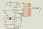
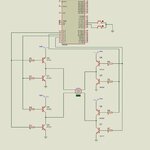
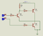
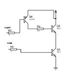
i am using transistors 2n2222, as it is part of assignment. and 2 switches as input to select turning on one of the 2 sides.
Now, please review the attached image and guide me, What i m doing wrong??
waiting for replies, please reply..............
 

Attachments

  • stepper using 89c51.jpg
    stepper using 89c51.jpg
    70 KB · Views: 180

Can you post your simulation files (.DSN) and your sourse code as well - the one compiled (just in case i dont have the compiler) as well as the one that havent
 
First of all you should always use a current limiting resistor in the base of each transistor, a value about 1k (5ma @ 5v) should do (depends on the transistor and output current).
If you don't use a resistor in the output of the avr you will BURN the port of the avr because of the high current.
Check with micro-controller data sheet for the pin maximum current, then divide 5v/current(A) to find the resistor.

You have used NPN transistors 1,3,5,7 with positive supply (maybe 12v) in the emitter and since you need to drive the base with a more positive voltage to turn the transistor on there is no way this is going to happen with 0 or 5v.

You should try something like CircuitPlanet: H-bridge circuit using NPN transistors
Or you can use pnp and npn bridge PocketMagic » A simple H-Bridge design

Alex
 
Last edited:

Can you post your simulation files (.DSN) and your sourse code as well - the one compiled (just in case i dont have the compiler) as well as the one that havent

Here is the attachment of the program in form of notepad file, and compiled HEX file (it is in compressed format).
 

Attachments

  • stepper controller.txt
    1.4 KB · Views: 79
  • new.rar
    359 bytes · Views: 118

You have used NPN transistors 1,3,5,7 with positive supply (maybe 12v) in the emitter and since you need to drive the base with a more positive voltage to turn the transistor on there is no way this is going to happen with 0 or 5v.

[/url]

Alex

Boss, i got your point of Current limiting resistors, and i had also a loook at your refered Links of H- bridges, but
as above you have mentioned that
"
You have used NPN transistors 1,3,5,7 with positive supply (maybe 12v) in the emitter and since you need to drive the base with a more positive voltage to turn the transistor on there is no way this is going to happen with 0 or 5v.

Alex
" but when i take my voltages of emitter lower than the BASE, still it won't work,
I have also made the Motors operating voltage less,
Still it won't work.
Any more suggestions??
Please reply!
 
Last edited:

" but when i take my voltages of collector lower than the BASE, still it won't work

I never said anything about the collector.

I think you should read about transistors here Tutorials, Electronics made EASY, Williamson Labs


In your case your circuit would work fine if you set the emitter voltage to 3v but you also have to set the motor voltage to a low voltage as well (about 2v).

I have attached a working circuit

Alex
 

Attachments

  • Hbridge.zip
    16.7 KB · Views: 118

Sorry bro!
I mistakenly wrote "Collector" in place of "Emitter".
Please read my above post once again, as it is re-edited.

---------- Post added at 17:43 ---------- Previous post was at 17:39 ----------

In your case your circuit would work fine if you set the emitter voltage to 3v but you also have to set the motor voltage to a low voltage as well (about 2v).


Alex

I have already done that, but of no success...........

In your case your circuit would work fine if you set the emitter voltage to 3v but you also have to set the motor voltage to a low voltage as well (about 2v).


Alex

Which version of Proteus are you using, because i have a little older version 7.4 and it says that i have later version, so i can't open the file in my software,
if u can tell me the version, I get that and then open it,
Please reply!
and thanks for all of your replies till now,
You have really been co-operative.
Thanks once again........
 
Last edited:

v7.7

I have attached a photo of the schematic, just set your motor to 2v
The four power supply are 3v

Alex
 

Attachments

  • hbridge.jpg
    hbridge.jpg
    147.5 KB · Views: 154

You may also find interesting Stepperworld Bipolar Tutorial

There are three ways to drive the bipolar motor, you are using the first.


Also in real world application you have to add a small delay (5-10us) between steps (turn all transistors off ) because there is a small delay from the moment you stop driving a transistor until it closes and if the second transistor of the pair opens before the other closes you will have a short circuit.

Alex
 

There are three ways to drive the bipolar motor, you are using the first.


Alex

understood very well,
Also in real world application you have to add a small delay (5-10us) between steps (turn all transistors off ) because there is a small delay from the moment you stop driving a transistor until it closes and if the second transistor of the pair opens before the other closes you will have a short circuit.

Alex

ok, this means, i have to generate some small delay, like some hundred cycles.....
thanks once again,
i'll reply in 2 hrs, after i make and check the working....
thanks
 

yes boss!
it is tested and found working,
really thankfull to you......
i have just 2 more questions, 1st is that, what might be the reason that my circuit was not working?? after i have changed the circuit just like your's except the addition of resistors(resistors not installed) ??
although resistors are needed for voltage drops and in software, there is no problem of burning of ICs, so it does not matter , whether we add resistors or not......what can be the reason???
and
2nd
did you changed any thing from program???
i have also used my own and it works fine...... now i wanted to know that whether u have changed the program, u provided in your "H-Bridge" rar file, i wanted to ask that i have written program for my own logic but you have changed the circuit connection.??? so how can my logic work in your circuit??
will you please guide me.......
 

what might be the reason that my circuit was not working??
I'll have to check your schematic again to answer that question, I'll get back to you

did you changed any thing from program???
so how can my logic work in your circuit??

I have used your .hex file , i didn't change anything, i have just connected 4 probes to your output pins to draw the output waveform and then i have connected the transistors as needed to create the step sequence.

Alex

---------- Post added at 11:16 ---------- Previous post was at 11:05 ----------

OK, i just checked your schematic, Proteus model needs for some reason to drive all 4 pins of the motor to work so instead of driving 2 transistors like you (which will work in a real motor) i drive 4 transistors , 1 is on and the other 3 off.

Alex

---------- Post added at 11:35 ---------- Previous post was at 11:16 ----------

from a second view in your schematic you were also driving the wrong pins of the motor, coil A is on the left and coil B on the right and not the 2 upper and 2 lower pins, so you were driving 2 different coils.
I get confused sometimes too but there is a very easy way to sort this, click on the component and select decompose, then when you move your mouse pointer over any of the pins you can see their names in the status bar (A1,A2,B1,B2 for the motor)
Maybe i should make a patent of this :-D
Alex
 

[/COLOR]OK, i just checked your schematic, Proteus model needs for some reason to drive all 4 pins of the motor to work so instead of driving 2 transistors like you (which will work in a real motor) i drive 4 transistors , 1 is on and the other 3 off.

Alex

understood that very well,
that's great.......
@@@@@@@@

[/COLOR]from a second view in your schematic you were also driving the wrong pins of the motor, coil A is on the left and coil B on the right and not the 2 upper and 2 lower pins, so you were driving 2 different coils.
I get confused sometimes too but there is a very easy way to sort this, click on the component and select decompose, then when you move your mouse pointer over any of the pins you can see their names in the status bar (A1,A2,B1,B2 for the motor)
Maybe i should make a patent of this :-D
Alex
now that was the real problem, i had,
after seeing the connections you made to motor, this came to my mind, and i composed a paint file to ask you the same thing , ( file is attached ), but now i had understood that..........
thank you very much................
and one more thing, I am thinking of making Hardware circuit for the motor above...........
what are the things, i should care about???
except resistors( to limit current) etc.....
 

Attachments

  • bipolar stepper motor question.bmp
    1.7 MB · Views: 97

First of all this circuit can only be used with low voltage motor (2-3v), if the motor is 12V then you have to use 2 transistors in the upper part of the 4 pairs, the second transistor will give 0 or 12v to the base of the (upper)transistor that you are using now (like the link i gave you before).

Depending on the current that you need you will have to use a stronger transistors or if you choose you can get a ready H bridge IC and save all the space plus get extra functions (overhead shutdown, current limit, short-circuit protection etc).

Also the resistors may need to have lower value depending on the beta of the transistor (so that the output current is enough) but always below the avr current limit.

I think you also need to use diodes in the opposite direction (cathode in the emitter and anode in the collector) to protect the transistors (all of them) from the reverse current of the motor (which is a big coil).

You can also make a mosfet bridge which will have lower losses (less heat because of lower resistance when they are on ) but care must be taken because you need to be able to give enough current to charge the mosfets (so you need a driver) fast or they will overheat because the switch on takes too much time (they should be on or off , when they are in a middle state the V*I watts is high).

I'm not that experienced , its just a hobby so I'm talking from the experience so far.
If this is a professional project you should get the advice of someone more experienced.

Alex

---------- Post added at 17:04 ---------- Previous post was at 15:30 ----------

This looks interesting...

PocketMagic » A simple H-Bridge design

Alex
 

First of all this circuit can only be used with low voltage motor (2-3v), if the motor is 12V then you have to use 2 transistors in the upper part of the 4 pairs, the second transistor will give 0 or 12v to the base of the (upper)transistor that you are using now (like the link i gave you before).


Alex

---------- Post added at 17:04 ---------- Previous post was at 15:30 ----------


Alex


I have a motor with specs.......
5V, 18 degree, it is a small floppy drive motor.
any suggesstions??
and thanks...........
 

Make the circuit i posted in the previous post (PocketMagic » A simple H-Bridge design) and you will be also be able to use stronger motors in the future (because 2955 and 3055 can handle the current).
You need two of these

Or you can something like the attached circuit (2 of them)
You can use whatever transistors suite you.
Also use the diodes in any circuit across the transistors.

Alex
 

Attachments

  • half_bridhe.jpg
    half_bridhe.jpg
    47.8 KB · Views: 144
Last edited:

Or you can something like the attached circuit (2 of them)
You can use whatever transistors suite you.
Also use the diodes in any circuit across the transistors.

Alex

Do i always have to use a PNP transistor, with one NPN,
can i not have both NPN's???
referring to the diagram provided........
 

hi here is the circuit for the same design, it may help you cheers
 

Attachments

  • motor driver.rar
    148.5 KB · Views: 119

You can use npn transistor without a problem, the resistor values depend on the transistors used and the current you need in the output.

Alex
 

Attachments

  • npn_half_h_bridge.jpg
    npn_half_h_bridge.jpg
    23.9 KB · Views: 137
  • npn_half_h_bridge2.jpg
    npn_half_h_bridge2.jpg
    22.9 KB · Views: 140
Last edited:

Status
Not open for further replies.

Part and Inventory Search

Welcome to EDABoard.com

Sponsor

Back
Top