Continue to Site

Welcome to EDAboard.com

Welcome to our site! EDAboard.com is an international Electronics Discussion Forum focused on EDA software, circuits, schematics, books, theory, papers, asic, pld, 8051, DSP, Network, RF, Analog Design, PCB, Service Manuals... and a whole lot more! To participate you need to register. Registration is free. Click here to register now.

Is there any way to design a 5v battery driven circuit to charge with USB?

Status
Not open for further replies.

Luckybuilding

Member level 1
Joined
Oct 8, 2005
Messages
40
Helped
2
Reputation
4
Reaction score
1
Trophy points
1,288
Activity points
1,615
Hi all,
I wanna make a designed circuit to work with battery and also charge with USB!
The circuit is designed to work with 5v & I wanna add the battery part without changing a large parts of it.

As I studied about it, I'm going to use a dual-cell polymer Li-Ion battery with a regulator. However, it would be great for this circuit to be able to be charged through USB cable.

Can you suggest any circuit to make this possible?

Thanks
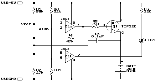
 

The Circuit
The heart of this charger is Z1a, one half of an LM393 dual voltage comparator. The output (pin 1) can be in one of two states, floating or low. While charging, the output is pulled low by an internal transistor, drawing about 5.2mA of current through Q1 and R5. Q1 has a beta of about 90, so about 470mA will flow through into the two AA cells being charged. This will fully charge a pair of 2500mAh cells in just over 5 hours.

34_1291759907.gif


13_1291760400.gif


During charging, R1, R2, and R4 form a three-way voltage divider which yields about 1.26V at the non-inverting input of Z1a (pin 3, Vref).

TR1 is a thermistor that is in direct contact with the cells being charged. It has a resistance of 10kΩ at 25°C (77°F), which varies inversely with temperature by about 3.7% for every 1C° (1.8F°). R3 and TR1 form a voltage divider whose value is applied to the inverting input (pin 2, Vtmp). At a temperature of 20°C (68°F), TR1 is about 12kΩ, which makes Vtmp about 1.76V.

Once the cells are fully charged, the charge current will literally go to waste, in the form of heat. As the cell temperature rises, TR1's resistance drops. At 33°C (91°F), the resistance will be about 7.4kΩ, which makes Vtmp about 1.26V, which equals the Vref voltage.

As the temperature rises above 33°C, Vtmp will become less than Vref, and the open-collector output of Z1a will float high. Therefore, the current flowing through R5 is greatly reduced, as it is now limited by R1, R2, and R4. As a result, the current flowing through Q1 and the cells is reduced to a 10mA trickle charge rate.

Also, because R4 is now connected to +5V through R5 and Q1 instead of being held at 0.26V by Z1a, the Vref voltage changes to about 2.37V. This guarantees that as the cell temperature drops, the charger won't turn back on. In order for Vtmp to reach 2.37V, TR1 would have to reach about 20kΩ, corresponding to a temperature of about 6°C (43°F), which should never happen in a room temperature environment.

Z1b is the other comparator on the LM393 chip, and a close look at the schematic reveals that it's performing the same comparison as Z1a. Instead of driving the charging transistor however, it drives an LED that indicates that charging is in progress. R6 limits current to the LED to about 10mA. By running the LED from its own comparator (which is on the chip whether we use it or not), the LED current has no effect on Vref.

Finally, C1 is there to ensure that charging starts when a pair of cells is inserted. With no cells in place and the charger off, C1 has about 1.9V across it (5V - 0.7V - Vref). As soon as the second of two cells is inserted, the positive side of C1 is suddenly forced down to the battery voltage (about 2.4V). This immediately forces the negative side 1.9V lower than this, to about 0.5V. Since this is connected to Vref, Z1a's output goes low, causing charging to start. After a few milliseconds, C1 adjusts to the new voltage difference imposed by R1, R2, and R4 on one side and the cells on the other, and no longer affects the circuit.

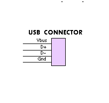
31_1291761050.gif


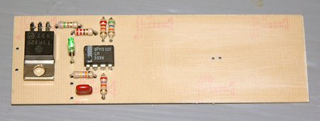
5_1291761262.jpg


Part Description
R1 56kΩ ¼W, 5% resistor
R2 27kΩ ¼W, 5% resistor
R3 22kΩ ¼W, 5% resistor
R4 47kΩ ¼W, 5% resistor
R5 750Ω ¼W, 5% resistor
R6 220Ω ¼W, resistor
TR1 10kΩ @ 25°C thermistor, approx. 3.7%/C° NTC
Radio Shack #271-110 (discontinued†)
C1 0.1µF 10V capacitor
Q1 TIP32C PNP transistor, TO-220 case
Z1 LM393 dual voltage comparator IC, DIP
LED1 Red, green, or yellow LED, 10mA
Other 2-cell AA battery holder
USB cable
Small heatsink
 

    V

    Points: 2
    Helpful Answer Positive Rating
Fidelis Anyanti,
is this circuit suitable for mine design as well? i'd design a micro hydro generator which able to generate 7v and 17mA. Can i use this as the input of the circuit u suggest? so that i can store the generated power.
thx :)
 

If you want to charger a dual-cell battery with 5V USB, I think you have to have a Boost circuit.
 
  • Like
Reactions: cyteh

    cyteh

    Points: 2
    Helpful Answer Positive Rating
If you want to charger a dual-cell battery with 5V USB, I think you have to have a Boost circuit.

Is that the boost circuit is used to boost up the current? will it effect the generated voltage?
Do u have any suggestion for the boost circuit?
Thx :)
 

Boost circuit will boost up the voltage. For charger, you can implement two ways: 1) boost circuit with current feedback. 2) boost circuit with voltage feedback+linear charger (to control charging current).
 

Thx, Leo.
Btw, may i noe any method to boost up the current?
Since the current that my prototype generated is only 17mA which is not high enough to charge up a battery.
 

Status
Not open for further replies.

Part and Inventory Search

Welcome to EDABoard.com

Sponsor

Back
Top