Continue to Site

Welcome to EDAboard.com

Welcome to our site! EDAboard.com is an international Electronics Discussion Forum focused on EDA software, circuits, schematics, books, theory, papers, asic, pld, 8051, DSP, Network, RF, Analog Design, PCB, Service Manuals... and a whole lot more! To participate you need to register. Registration is free. Click here to register now.

How to drive a LED with DAC?

Status
Not open for further replies.

grabbo

Newbie level 6
Joined
Oct 6, 2009
Messages
14
Helped
1
Reputation
2
Reaction score
1
Trophy points
1,283
Activity points
1,395
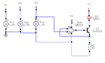
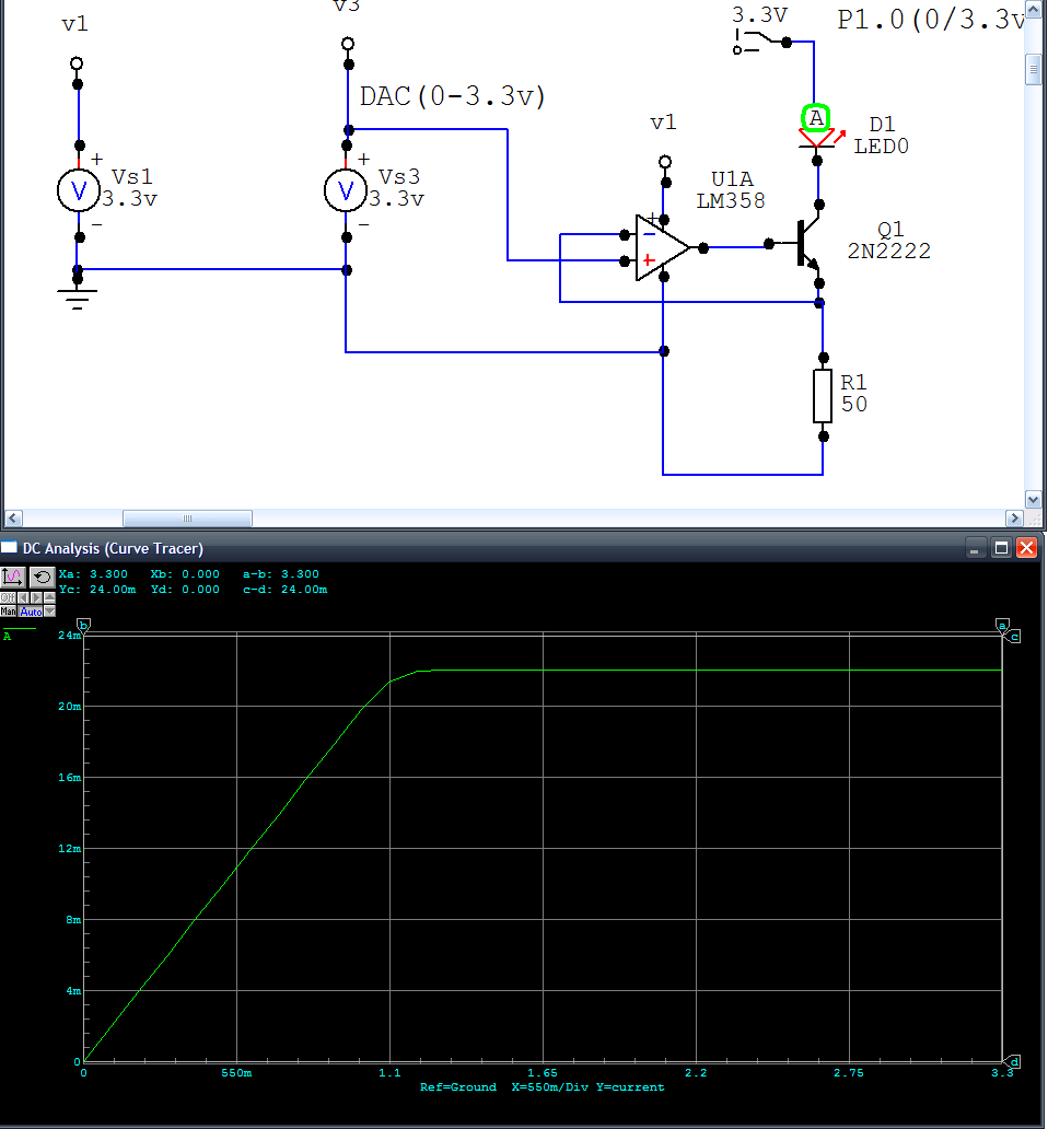
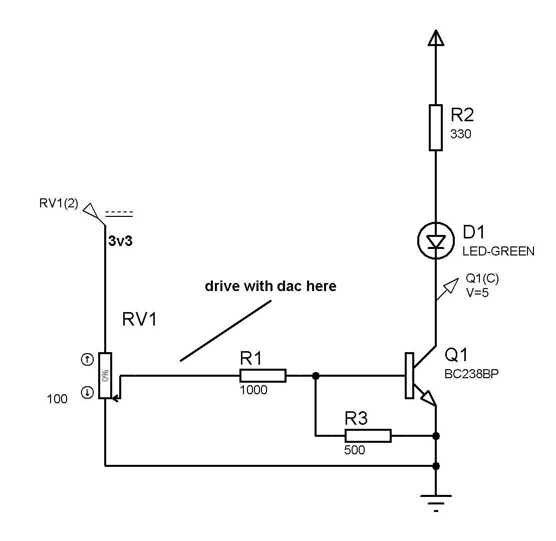
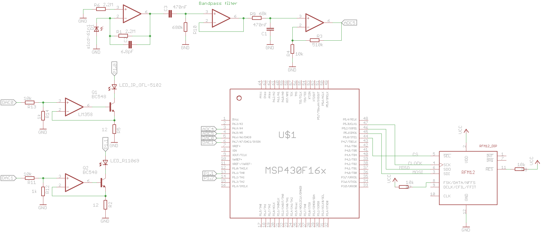
I drive LED with DAC from microcontroller because i want to adjust the brightness of LED.
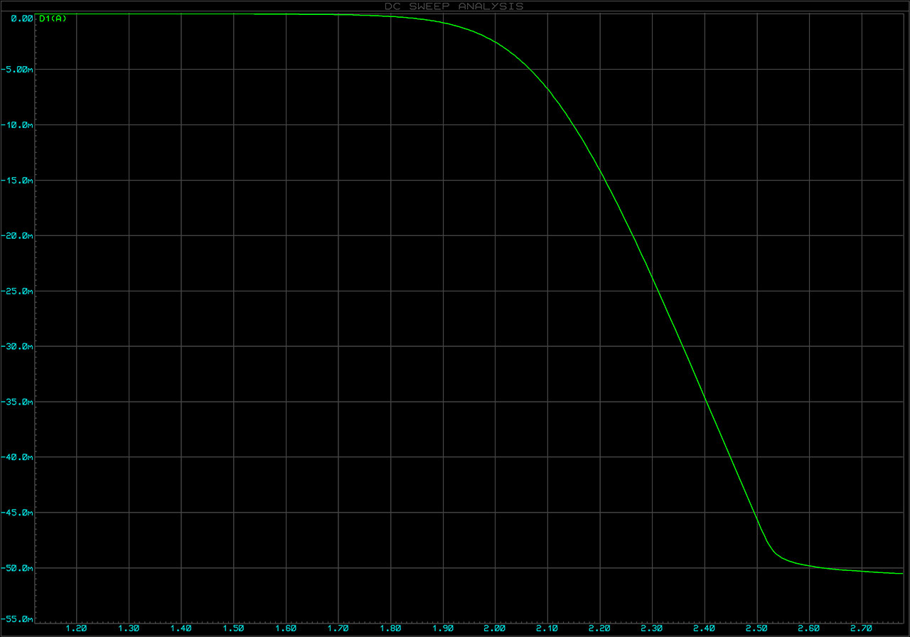
I simulated the connection on the image in Circuit Maker and LTSpice,it doesnt work with 3.3v on the LED (v2). with 5/6.6v works as it should. My microcontroller supply is 3.3V.

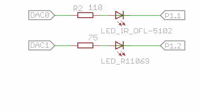
Any other ideas how to drive led?:cool:
 

Attachments

  • led_dr.PNG
    led_dr.PNG
    9.9 KB · Views: 322

Re: LED driving with DAC

Buy a boost converter type driver with an analog control
input. Higher-color (and white) LEDs need more than 3V
forward to light.
 

Re: LED driving with DAC

Thx, i was playing with leds in Circuit Maker,accidentally changed LEd to Blue. I use only RED/INFRAREd which got Vf max 1.7V. The led in this circiut got Vf=1.7V.
Do you think it will work if P1.0 is pin output which should turn on/off the LED and DAC drives LED brightness.


You are not going to get much brightness range as it is. The problem is that for maximum brightness you will drop 3.3V across the 50 resistor (or try to) which leaves nothing for the LED.

The solution is simple. Drop the 50 ohms by, say, a factor of 10. Then add a potential divider to drop the DAC output by a factor of 10 to the opamp input. Then you only lose 0.33V at maximum brightness. Mind you, those sales give you 66mA maximum which seems a bit high.

Keith
 

Just a suggestion, shouldn't you be using a PWM rather than a DAC. The voltage-current response of a LED like that of any diode is highly non linear!!! Dac wont have such a fine resolution to effectively control LED brightness.

Asimov
 

But that circuit is a constant current drive! It will be fairly progressive. A PWM is a good alternative (and simpler for the hardware) but a constant current drive also works well.

Keith
 

Thx for your responses, I found a solution.
This one is simple and range is as i need.
 

Attachments

  • led_driver.PNG
    led_driver.PNG
    37.4 KB · Views: 244

Make sure your opamp can drive the current - that was why the circuit with a transistor is useful. Also, make sure that you have a realistic voltage drop across the diodes in your simulation - you may find that with 1.7V drop you cannot get the current you are showing (45mA with 3.3V input). I am suspicious of your opamp model At 45mA and 75 ohms that is 3.375V so where is the voltage across the LED coming from?

Keith.
 

yes,the model was not set properly. It gives worse range as with transistor. I'll check how to drive LED's with PWM and ill inform you about results
 

You could always do what I suggested earlier "The solution is simple. Drop the 50 ohms by, say, a factor of 10. Then add a potential divider to drop the DAC output by a factor of 10 to the opamp input. Then you only lose 0.33V at maximum brightness."

Keith.
 
  • Like
Reactions: grabbo

    grabbo

    Points: 2
    Helpful Answer Positive Rating
You could always do what I suggested earlier "The solution is simple. Drop the 50 ohms by, say, a factor of 10. Then add a potential divider to drop the DAC output by a factor of 10 to the opamp input. Then you only lose 0.33V at maximum brightness."

Keith.


Thx keith, you helped.
I tried your suggestion before with wrong calculation,therefore i abandoned it. :???:
I can't lower R because it would result in higher current. 47ohms set limit to 24mA.
Which transistor is fine for this application in to/dip package (on breadboard)?I'm limited in resources. Got BC548 at home.
 

Attachments

  • led_driver.PNG
    led_driver.PNG
    28 KB · Views: 163
Last edited:

You need to reduce R1 further to maybe 5 ohms but you also need to scale your DAC voltage a lot lower to the opamp input. The idea is to make the scaled DAC voltage equal the drop across R1. So if you want 40mA maximum and say 5 ohms for R2 then the voltage drop across R2 would be 0.2V at maximum current. So, you want the 3.3V from the DAC to be only 0.2V on the opamp non-inverting input. So around 150k for R2.

You need an opamp than can work at the negative rail for the circuit to work, but I think the LM358 can do that.

Keith.

---------- Post added at 21:43 ---------- Previous post was at 21:40 ----------

PS. any general purpose NPN will do. You need to just watch out for the power dissipation but if you are running at say 40mA maximum and 3.3V supply then even if all the power went into the transistor it would only be 132mW.

Keith.
 

I don't know your circuit but if you have a pwm output available in your micro controller you could use that instead of the dac

Alex

---------- Post added at 22:10 ---------- Previous post was at 21:54 ----------

Or you can use this circuit with a volage divider in the input of the transistor, I have used the variable resistor in the input to simulate the dac
You can change R2 to a lower value depending on your led and how much you want the maximum current to be.


Alex
 
Last edited:

Or you can use this circuit with a volage divider in the input of the transistor, I have used the variable resistor in the input to simulate the dac
You can change R2 to a lower value depending on your led and how much you want the maximum current to be.

Alex

The PWM is a good idea. The other circuit will not be very linear, if that is important.

Keith.
 

If he wants to use the full range of the adc you are right, if not he can control the current in about half the range of the dac.
I have simulated my circuit, you can see the input voltage and led current with a 50 ohm resistor


Alex
 

Yes, but it will be very dependant on transistor beta, temperature and LED characteristics. It all depends on the specification. A linear system would need to be a constant current drive or PWM.

Keith.
 

It's working but it's slow.I switch 2 LED's every 1ms. How could i improve the speed ?

It was working nicely when i connected DAC output to the LED's cathode and PIN output to the LEDS anode. Pin output switched every 1ms, output on photodiode was good as expected. That was not properly driving led but it worked. :D
 

I don't see a way that the opamp circuit can affect the switching speed of the led.
Did you change anything else?
You can check the speed of the opamp with a 3v square wave in the input.
If i understand correctly you had connected the led between the dac and a pin of the micro controller, if so you were probably switching in double rate because you could switch the led off both by the dac and the uc pin.

Alex
 

The circuit should be able to switch at 100kHz easily, even with the LM358. Are you sure you aren't being limited by the DAC/software? What happens when you try to switch faster?

Keith.
 

The circuit should be able to switch at 100kHz easily, even with the LM358. Are you sure you aren't being limited by the DAC/software? What happens when you try to switch faster?

Keith.

I'm working on the problem today. I went back to my experimental schematic which is this :
47_1290877779.png

P1.1 and P1.2 are turn off/on every 1ms. ( P1.1 ON/P1.2 OFF (1ms),P1.1 OFF/P1.2 ONN(1ms), P1.1...). DAC is constant voltage.
Oscilloscope shows the output.
When i connect it with LM358 and NPN transistor BC548, i've got delay about 1.5secs.
Here's screen, yellow color is the voltage on LED and green is photodiode output, grid is 0.5s or 2Hz per one.


The whole schematic just in case u find something,


Software is good,i checked switching the ouput frequency, DAC output switching not PIN as well tried. Always with delay.What else could i check?
I suspected something wrong with photodiode , but it's working with my experimental schematic which is not exactly driving the LEDs brightness.
 

Status
Not open for further replies.

Part and Inventory Search

Welcome to EDABoard.com

Sponsor

Back
Top