Continue to Site

Welcome to EDAboard.com

Welcome to our site! EDAboard.com is an international Electronics Discussion Forum focused on EDA software, circuits, schematics, books, theory, papers, asic, pld, 8051, DSP, Network, RF, Analog Design, PCB, Service Manuals... and a whole lot more! To participate you need to register. Registration is free. Click here to register now.

Help!! LC filter for Chopper

Status
Not open for further replies.

CandleCookie

Advanced Member level 4
Joined
Aug 25, 2010
Messages
102
Helped
11
Reputation
22
Reaction score
11
Trophy points
1,298
Location
Malaysia
Activity points
2,069
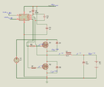
I had calculated the ripple current for this circuit but the answer does not match with my simulation results. Can anyone help me to check my equations?
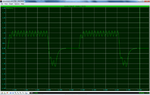
I obtained ripple current to be 3 but simulation shown the ripple current is 0.5.
 

Attachments

  • Untitled2.png
    Untitled2.png
    127.5 KB · Views: 92
  • Untitled1.png
    Untitled1.png
    114.9 KB · Views: 89
  • Untitled3.png
    Untitled3.png
    25.6 KB · Views: 80

It is unclear what point the scope simulation plot is of. It appears to be related the MOSFET output chop voltage. It is definitely not a plot of coil current.

If you are looking for battery ripple current you are going to have to put in representative resistance of output filter cap and battery Rs resistance. You should also put in coil resistance.

The equation is for very simple first pass estimate only true for idea components. Your sim at least has the real Rs of the MOSFET's which is enough to cause result to be different then the simple equation.
 

I'm measuring the battery current which is C1(1). Inside the 12V battery, i set the internal resistance to be 0.1.
Do u mean that I should put another resistance at the output?
 

Status
Not open for further replies.

Similar threads

Part and Inventory Search

Welcome to EDABoard.com

Sponsor

Back
Top