markdem
Member level 3
Hi All,
I thought this was going to be easy, but I was wrong. I have a dual rail power supply that I would like to add some voltage and amp display to. As I would also like to do some logging, I thought doing both with a PIC is the way to go.
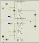
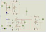
The voltage part is fine, it is the current path that is getting me. As the power supply will be low power (under 2 amps) I was just going to use a shunt (.1 ohm 10w resister). I just have to measure the voltage drop. I can do it on the positive rail, but the negative rail is giving me different outputs. Please see the attached file for my circuit. I just can’t work out why the negative is different. I have tried to swap the inputs and change the feedback to positive, but I still am getting outputs that don’t match what I am measuring.
Can anyone help me out with this one?
Thanks
Mark
I thought this was going to be easy, but I was wrong. I have a dual rail power supply that I would like to add some voltage and amp display to. As I would also like to do some logging, I thought doing both with a PIC is the way to go.
The voltage part is fine, it is the current path that is getting me. As the power supply will be low power (under 2 amps) I was just going to use a shunt (.1 ohm 10w resister). I just have to measure the voltage drop. I can do it on the positive rail, but the negative rail is giving me different outputs. Please see the attached file for my circuit. I just can’t work out why the negative is different. I have tried to swap the inputs and change the feedback to positive, but I still am getting outputs that don’t match what I am measuring.
Can anyone help me out with this one?
Thanks
Mark