Continue to Site

Welcome to EDAboard.com

Welcome to our site! EDAboard.com is an international Electronics Discussion Forum focused on EDA software, circuits, schematics, books, theory, papers, asic, pld, 8051, DSP, Network, RF, Analog Design, PCB, Service Manuals... and a whole lot more! To participate you need to register. Registration is free. Click here to register now.

[SOLVED] Hspice Instability High amplitude and frequency spikes

Status
Not open for further replies.

fcfusion

Full Member level 4
Joined
Mar 6, 2010
Messages
203
Helped
43
Reputation
86
Reaction score
24
Trophy points
1,298
Activity points
2,826
Hi guys

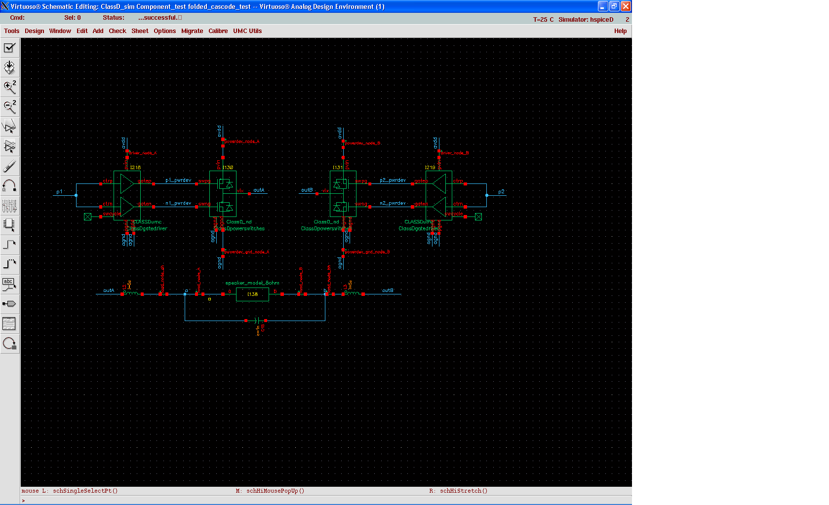
I'm testing a Class D amplifier output stage and I'm having some troubles with the simulations. The simulation runs fine in the beginning but after a while the output voltage at the load's pins starts to oscillate with very sharp spikes and increases up to several KiloVolts!!! Once it starts to oscillate, the simulation because very slow.

I suspect it is caused by the LC components and 've tried changing timestep, Method=GEAR, GMIN, RSHUNT and all that stuff but the circuits still reaches several kV!!!

The circuit is composed by an H-Bridge and Drivers, a low pass filter and the 8 Ohm load. The H-bridge is driven by an ideal source.

Any help is apreciated


"Ideal" sources are the likely cause. An ideal current source, for example, will have no limit to the voltage they will use to achieve the current, unlike real life. Try tracing the problem voltages back to find out where they originate.

Keith.
 

Have you tried to add a small resistor between the inductor and the 8-ohm load?
 

"Ideal" sources are the likely cause. An ideal current source, for example, will have no limit to the voltage they will use to achieve the current, unlike real life. Try tracing the problem voltages back to find out where they originate.

Keith.

Tanks for your replies

I doubt the voltage source is causing the issue since it isn't connected to the LC componentes directly. It as a lot of components in the middle, the Drivers and Power Devices. Besides that, I have no current sources in the schematic. Anyway I think I'll test it with a Port instead of a VDC source, just in case.

Have you tried to add a small resistor between the inductor and the 8-ohm load?

Yes, and it solves the stability problem. However, I'm trying to determine the Output Stage distortion and it is very important that the output filter is lossless. I was hoping the problem could be solved through some configuration, without requiring aditional circuits..
 

Well, where are you going to buy a lossless inductor or
capacitor? Right. Go for realism instead.

Your "lossless" filter has therefore infinite Q and you'll
ring it up infinitely with ideal switches. Getting the
behavior you describe.

May as well treat the output stage and a realizable
filter as an assembly, because neither is worth anything
without the other and they need to be co-optimized.
 

Yes, and it solves the stability problem. However, I'm trying to determine the Output Stage distortion and it is very important that the output filter is lossless. I was hoping the problem could be solved through some configuration, without requiring aditional circuits..
As dick_freebird wrote, you won't find an ideal filter for your testbench. Adding a small resistor, say 0.3-2ohm (depending on the package type, trace length) is only modeling the resistance of the pins/wires and inductor coil, reducing the Q of your filter as in a real circuit. Depending on the frequency of operation, you might also want to model the parasitic capacitance of the same components. Doing so, you simulate your design closer to your measurement environment. If not, you'll have some ugly surprises in the lab...
 

Well, where are you going to buy a lossless inductor or
capacitor? Right. Go for realism instead.

Adding a small resistor, say 0.3-2ohm (depending on the package type, trace length) is only modeling the resistance of the pins/wires and inductor coil, reducing the Q of your filter as in a real circuit. Depending on the frequency of operation, you might also want to model the parasitic capacitance of the same components. Doing so, you simulate your design closer to your measurement environment. If not, you'll have some ugly surprises in the lab

I am aware of all this. I'm performing simulations with some ideal components, such as the output filter, because I'm analysing the influence of each of the Class D amplifier block to the output signal distortion. I suspect the H-bridge and/or Drivers are causing most of the distortion and therefore I must test it under some ideal conditions. If I add resistors in series with the inductor and the circuit exhibits distortion, the question remains: do the resistors influence distortion? Or is just the H-Bridge?

I'm just trying to tackle each problem separatelly. I know very well that even if I achieved an incredible THD=120dB under simulation, the real circuit performance would be a lot worse. But at least I would know which block is causing me problems.

I'm going to try your sugestions anyway and see if I can get good results.
 

I've discovered the source of the problem and I'm posting it for anyone who needs it.

The instability is caused by the output LC filter, because Hspice does not handle series capacitors well. I found the answer on page 7 of the following document:

http://www.intusoft.com/articles/converg.pdf


In fact, the capacitor is in series with two inductors, thus causing instability. If the capacitors are connected in parallel, with one pin connected to ground, the simulations runs smoothly.

Hope it helps anyone with the same problem
 
  • Like
Reactions: erikl

    erikl

    Points: 2
    Helpful Answer Positive Rating
Status
Not open for further replies.

Part and Inventory Search

Welcome to EDABoard.com

Sponsor

Back
Top