sjamil02
Member level 4
- Joined
- Nov 8, 2009
- Messages
- 72
- Helped
- 9
- Reputation
- 18
- Reaction score
- 5
- Trophy points
- 1,288
- Location
- United Kingdom
- Activity points
- 1,961
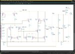
I tried to design a shunt regulator for digital power supply. The schematic is as attached. However I'm not sure whether my simulation method is correct or not. For the input current, I used series resistor (100mOhms) with 1V dc source from external power supply. (I'm not sure how to set the input current as I do not know how to define the spec for this one. 100mOhms resistor is from package modelling information i.e. Rball+Rpackage=100mOhm)
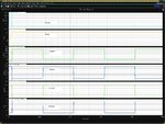
The loading current is a pulse current source from 0mA-->20mA. The result looks not right to me. The vreg voltage looks very flat as if no regulation happen. And the regulator circuit is without compensation just for inital design test.
Please advice.
Thanks in advance
SJ
The loading current is a pulse current source from 0mA-->20mA. The result looks not right to me. The vreg voltage looks very flat as if no regulation happen. And the regulator circuit is without compensation just for inital design test.
Please advice.
Thanks in advance
SJ