Continue to Site

Welcome to EDAboard.com

Welcome to our site! EDAboard.com is an international Electronics Discussion Forum focused on EDA software, circuits, schematics, books, theory, papers, asic, pld, 8051, DSP, Network, RF, Analog Design, PCB, Service Manuals... and a whole lot more! To participate you need to register. Registration is free. Click here to register now.

High Speed IR photodiode switch circuit

Status
Not open for further replies.

joonasreunamo

Newbie level 5
Joined
Oct 24, 2010
Messages
8
Helped
0
Reputation
0
Reaction score
0
Trophy points
1,281
Activity points
1,348
Hello, Im looking for help to the following problem:

Im sending timing signals with directed narrow angle IR leds. When IR LED switches on I should detect signal with +5V or +3.3V GPIO pin. Most important is to get constant time, lets say±10ns, between IR present and detection. It wouldnt hurt to get long range (3-4m) too.

First issue: Photodiode
Currently I have Osram SFH 2400FA. Can anyone say is it good? It had 5ns risea and fall times but the rest does not say too much to me.

Main issue: getting out digital signal
I tried to build a circuit like in (insert http..) vorlon.case.edu/~flm/eecs245/Datasheets/Sharp%20photodevices.pdf Figure 3
(A). Photodiode simply operates transistor. I used 20V reverse voltage. Pull-up (RL) was 100kΩ to 20V source and RBE was around 10MΩ (finger to finger) ;-)

From 30cm range it worked. 50cm it faled. No idea how fast it is (no test bench yet).

Which transistor would be fast enough and suitable for the circuit? (I order from Farnell)
How should I determine resistors RL and RBE?

Thanks!

Im newbie so try to answer with terms I have a chance to decode with google. :roll:
 

The SFH2400 is OK.

I don't know why you want 10ns precision, but you won't get it with the circuit you refer to in the data sheet. Well, maybe with a 50 ohm load you might, but with RBE=10M you will more likely be something like 100us or slower. To get 10M ohm with 10ns response time will be a tall order in a single stage even with a good transimpedance amplifier. A more likely solution would be to keep the gain low in the first stage and add gain in later stages as required. You need to use a transimpedance amplifier so the photodiode sees a low impedance though, not a simple amplifier as you are using. Think of the effect of the photodiode capacitance with the load resistor - that time constant is huge.

You don't mention the ambient light issues but if you have such a high gain in a DC coupled system then the circuit will easily saturate from ambient light and you will receive nothing.

Keith.
 
This is to get 2 posts to be able to add a link :p

---------- Post added at 22:49 ---------- Previous post was at 22:48 ----------

Hmm.. capacitanse.. load.. transimpedance... my circuit and 10Mohms was just trial and error.

OK I lower my demand to 1us! 8) ..let's tweak later.

Photodiode (or 1-5 to enhance angle of detection) forms a that should be small. Any extra components (and complexity) should be avoided.

What could be a good circuit design?

I picked up LM7171 from National Semiconductor as an op-amp. Is that good enough without extra "stages"(?). Or would a FET manage the situation within 1us?

I still cannot comprehend how to calculate resistors and capacitors to transistor or op-amp switch. Anyone has a link or advice?
**broken link removed**

Currently we can assume relatively small amount of ambient IR if I use filters with lamps.
 

Your link doesn't work for me.

LM7171 wouldn't be my choice for your specification.

What output do you want from the circuit - and analogue one or digital?

Keith
 
I simply want to detect an edge of IR light field => digital output. Signal will be connected to GPIO of Altera DE2 FPGA board.

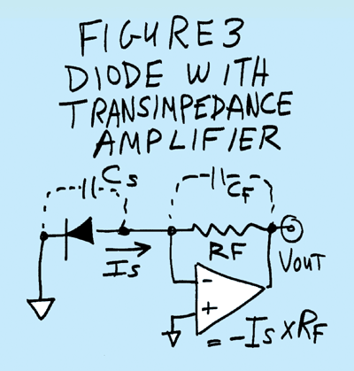
This was the image of suggested op amp circuit from electronicdesign.com by Bob Pease. Calculations for capacitors and resitors were not for switch but for analog design (as far as I undersood).
62_1288037794.gif
 

Yes, the transimpedance amplifier like you have shown is a better way of trying to get high gain (transimpedance) and speed because it presents a low impedance to the photodiode. Here are a couple of examples with different feedback resistors. The initial gain stage is usually made as high as possible for best signal to nosie ratio, but a high bandwidth usually results in a low feedback resistor. You can then amplify the output signal further with other gain stages.

Keith.
 

Attachments

  • AD8655 transimpedance 2k2.pdf
    6.3 KB · Views: 150
  • AD8655 transimpedance.pdf
    7.9 KB · Views: 133
Ahaa. Gain and bandwidth are bound together, so higher gain means lower bandwidth and lower bandwidth grater feedback resistor and greater resistance greater latency. I learn!

1) But in this circuit there is no 20V reverse voltage. Doesn't that make photodiode considerably slower?

2) Does V3 voltage source stand for ground and VB a connection to ground? Just to be sure.

3) If ambient light triggers the switch what should I do?

I'll buy parts tomorrow and get on testing.
 

Sorry, those circuits are a bit of a jumble as they have been used for several explanations - single rail, dual rail high speed, low speed etc.

Normally I would reverse bias the photodiode to reduce capacitance although for large area devices the leakage under reverse bias can be more of an issue. The bias voltage to the non-inverting input can be 0V if you use dual rail. The non-inverting input and photodiode don't have to be the same.

If ambient light could saturate it then you need to consider modulating the light source, keeping the initial stage gain low, AC coupling and bandpass filtering.

Keith
 
Actually I don't even know how to apply bias with op-amp, but if the simple schema you provided will do the trick I will return with lots of smileys :)

Farnell could provide only AD8656. It has 2x AD8655 op-amps in one package. Could this second op amp be easily used to improve the circuit?
 

But can you tell what kind of resistors and capacitors I need for that? I have no EDA tool :(
 

The resistor determines the gain (which also has an influence on bandwidth). I assume at this stage you don't know what gain you need. The capacitor is usually chosen to be as low as possible while still giving stability. The easiest way to determine that is by simulation. The demo version of SIMetrix should help you do that. Analog Circuit Simulation Software from SIMetrix Technologies - SPICE

The two extreme cases in my simulations should give you an idea of the likely values.

Keith.
 

I got my test circuit up and running. I used the schema whit 6.8M resistor and produced -5V rail with LTC1046.

But why I got negative voltages from output? I cant use negative voltage.
 

The transimpedance amplifier is an inverting configuration - current in to the input pin will produce a negative voltage. If you need a positive voltage then you can either connect your photodiode differently or invert the signal in the next gain stage.

However, it sounds like you have too much light if the output is at -5V. You need to reduce the gain (transimpedance) by reducing the 6.8M resistor.

Keith.
 

Well "Signal will be connected to GPIO..." so I thought it was obvious I need 5V or 3.3V as logical 1. Singnal swings nicely between -0.05V - -4.90V

How should I connect the photodiode to get positive voltages. Does "differently" simply mean opposite direction?
 

Status
Not open for further replies.

Part and Inventory Search

Welcome to EDABoard.com

Sponsor

Back
Top