Continue to Site

Welcome to EDAboard.com

Welcome to our site! EDAboard.com is an international Electronics Discussion Forum focused on EDA software, circuits, schematics, books, theory, papers, asic, pld, 8051, DSP, Network, RF, Analog Design, PCB, Service Manuals... and a whole lot more! To participate you need to register. Registration is free. Click here to register now.

LC filter measurements

Status
Not open for further replies.

franken35

Newbie level 6
Joined
Feb 27, 2010
Messages
13
Helped
0
Reputation
0
Reaction score
0
Trophy points
1,281
Activity points
1,433
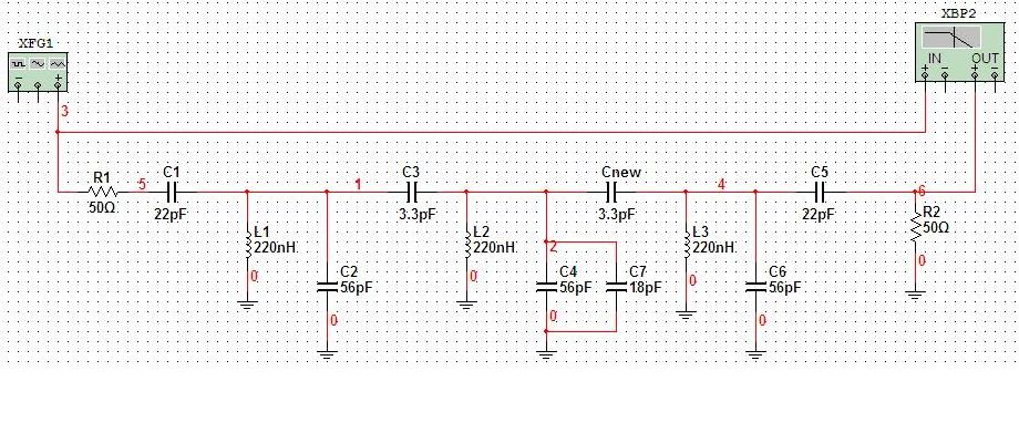
Hello, I have designed an LC bandpass filter. Now I am trying to assemble it on veroboard in order to test it. I received an advice to determine series loss resistance and add equivalent loading capacitor. However I don't know how to measure this series resistance. Does anyone know how to do it?

The way I am testing this filter is by inserting a signal into veroboard by signal generator and the output to spectrum analyzer. I have a simulation of my filter in multisim. I attached it.

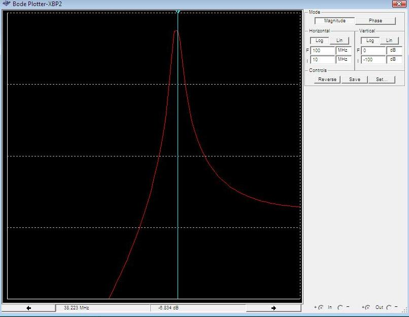
My center frequency is 38.2 MHz and the passband is 2 MHz. I used bandpass filter design with coupling capacitor to match the impedance and then changed the values slightly to find the appropriate components.

So could anyone let me know if the design if fine and how to determine the series loss resistance and I presume the equivalent loading capacitor I need to add it at the filter end to coupling capacitor, is it?


You have a three pole filter. With 22 pF at 38.2 MHz you are projecting a 767 ohms real load on either end.

The loss of the filter is primarily caused by coil Q. This can be modelled as Rp or Rs. You can measure unload Q for each coil by lightly coupling into a resonant tank made with the coil and appropiate value cap to resonate coil near 38.2 MHz. Measure 3 db bandwidth. Q = Center freq/BW 3db. Rp = Q* XL. Rs = XL/Q

Use two 100k resistors or two 0.2 pF caps to couple in and out of resonant tank.

I have no idea what your 220 nH coils look like but a reasonable Q would be >150.

The lower the coils' Q the more the coupling needs to be to accomplish a reasonable nose response. The value of the coupling caps takes you from a Bessel, through a Butterworth, then into a Chebyshev filter.

Bessel = undercoupled, rounded nose response. Linear phase.
Butterworth = maximally flat nose response.
Chebyshev = overcoupled, ripple in passband, higher selectivity for given nose bandwidth.

Might want to look up 'Deshal's filter tuning'.
 
Last edited:
Hello and thank you for responding so quickly.

I was using this example : Error Page 404) and Chris Bowick book for design. I am new to filter design, however for coupling capacitors I calculated them so the input and output is matched to 50 ohms. The filter impedance is 980 ohms. I used the following formulas:
Filter impedance ( Z ) = Qn X QBw X 2 X pi X Fo X L
Xc = SQRT [ Zfilt X Zin - ( Zin X Zin ) ]
The bandwidth is 2MHz, so the designed Q factor is 19.1. The coils i am using were purchased from Bec, here is datasheet:
**broken link removed**).

So as I understand - I measure one resonant tank at a time with 2 coupling capacitors or 100K resistors (check that I have 38.2 MHz, measure the 3 db BW on oscilloscope or spectrum analyzer, calculate Rp. Once I calculated Rp, I need to add an equivalent loading capacitor to each tank? So 3 extra capacitors just add it in parallel with 3 designed capacitors in each tank or obviously just substitute the 3 capacitor to new value?

Thank you again for information, it was very helpful. Yes, I haven't found any information on Deshal's filter tuning.
 

Hello again,

I have tried to test it, but the Q that comes up is pretty low, its about 5. However in the datasheet it is said that the minimum should be 45. I use TOKO coil 294SN-T1011Z (0.22uH). I presume I am not doing something right. I need 38.2 MHz, so I create a resonant tank with 79pf in parallel with the inductor and couple in and out with 100K resistors. I get a BW of about +- 6MHz., so the Q is around 3-5. I measure it applying the signal generator to the filter and use the output from spectral analyzer. I start at 38.2 MHz and sweep the frequency to find the 3db points.

Is that possible to have Q that low or I did something wrong? Or I just need to change the coupling?
 

Status
Not open for further replies.

Similar threads

Part and Inventory Search

Welcome to EDABoard.com

Sponsor

Back
Top