Continue to Site

Welcome to EDAboard.com

Welcome to our site! EDAboard.com is an international Electronics Discussion Forum focused on EDA software, circuits, schematics, books, theory, papers, asic, pld, 8051, DSP, Network, RF, Analog Design, PCB, Service Manuals... and a whole lot more! To participate you need to register. Registration is free. Click here to register now.

Gain + Phase compensation in folded cascode OTA-Cap integrator

Status
Not open for further replies.

samiurrehman

Member level 2
Joined
Aug 30, 2010
Messages
49
Helped
2
Reputation
4
Reaction score
2
Trophy points
1,288
Location
Pakistan
Activity points
1,729
Dear all,

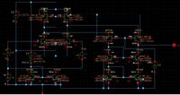
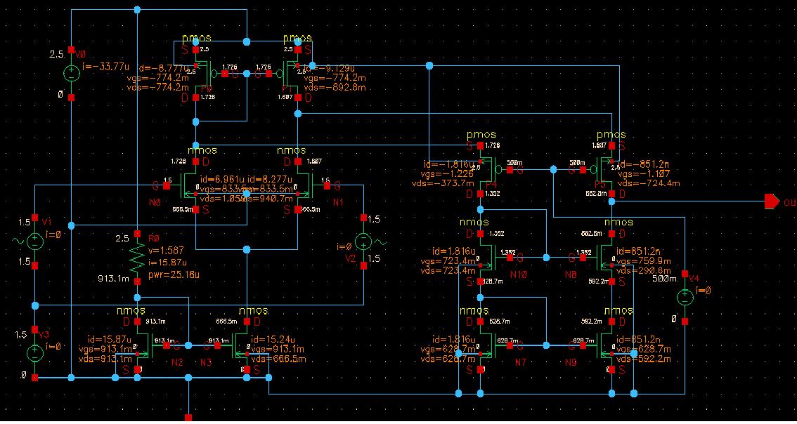
I am designing a high frequency integrator. The one i designed is as follows:


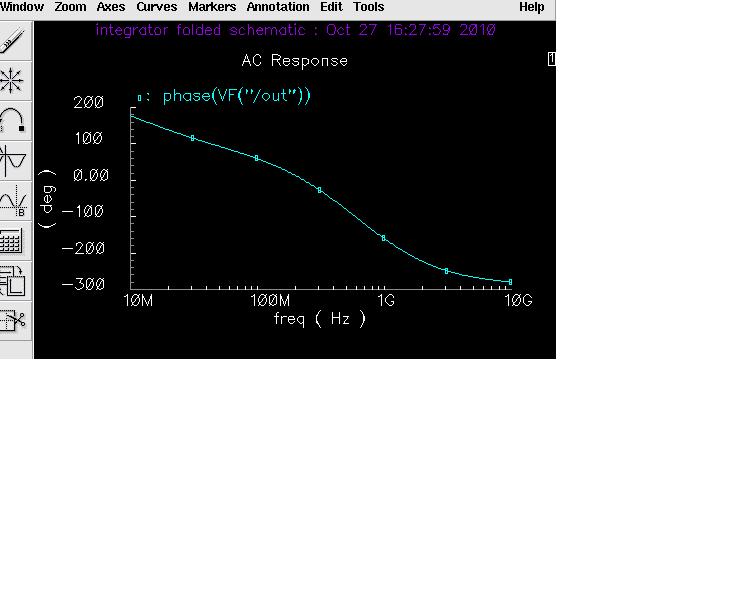
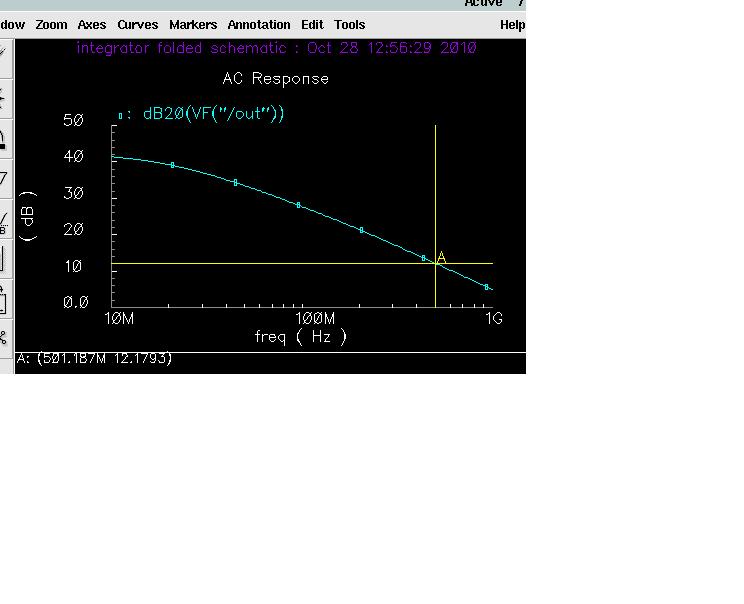
It has required magnitude frequency response but weird phase response, and when i connect the load capacitance the gain of magnitude curve drops below zero dB while the phase response remains as it is. I need compensation which can lift my magnitude graph above zero dB and also provide some phase compensation.
What kind of compensation do i need to adopt???
Regards
 

I dont think you have any compensation problem.

Most likely the load capacitor is messing up your DC Operation Point simulation. The amplifier is probably taking some time to charge the capacitor and the DC op point is calculated when Vout=0, when some of your transistors are in triode. There are two ways to overcome this problem:

1) set up initial conditions, setting the capacitor voltage to the expected amplifier DC voltage

2) increase the DC op point simulation time
 

I have plotted the phase response as below:


it is clearly an unstable integrator.....i need its phase response steady at 90degree around 2.5 GHz.....
 

Please post Magnitude plot and testbench circuit as well, so we can help you
 

    V

    Points: 2
    Helpful Answer Positive Rating
1.what's the purpose of PMOS current mirror ? It seems strange .
2.your testbench is not right for AC simulation.
 

Your OTA is railed: one output is at 1.3V while the other is at 0.66V. The problem seems to be at the input differential pair. Are your transistors sized properly?
 

the transistor sizes are fine.....here is the magnitude response:


i need to improve gain at at least 500MHz upto almost 50dB, rite now it is only about 12dB................the phase is the same as above, which also needs to be compensated.
 

i need to improve gain at at least 500MHz upto almost 50dB, rite now it is only about 12dB................the phase is the same as above, which also needs to be compensated.

Gain of 50dB at 500 MHz is very hard to achieve, you would require an incredibly high GBW. The integrator's gain is defined by the R and C feedback values, as long as the amplifiers can keep up with the gain and speed requirements.

If your amplifier has enough gain and GBW, you only need to decrease the capacitor's value to increase the integration gain. However, I seriously doubt you can achieve such an high gain at 500 MHz.
 

Status
Not open for further replies.

Part and Inventory Search

Welcome to EDABoard.com

Sponsor

Back
Top