kalbun
Full Member level 2
- Joined
- Oct 2, 2010
- Messages
- 134
- Helped
- 37
- Reputation
- 74
- Reaction score
- 36
- Trophy points
- 1,318
- Location
- Firenze, Italy
- Activity points
- 2,114
Hello everyone, this is my first "new thread" to the forum ")
Please have a look at this datasheet: it's a typical IF demodulator - or at least I saw several ICs almost identical.
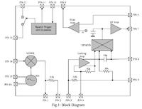
The filter opamp has only two pins accessible from outside. The positive input is always drawn as "floating". I think there is an interaction between positive input of the filter opamp and the AF amp output (demodulated audio), but I was unable to find more information on the datasheet.
Does anyone can explain me the internal connection of positive input, or lead me towards the right direction?
Thanks
Giuseppe
Please have a look at this datasheet: it's a typical IF demodulator - or at least I saw several ICs almost identical.
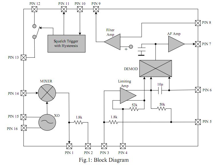
The filter opamp has only two pins accessible from outside. The positive input is always drawn as "floating". I think there is an interaction between positive input of the filter opamp and the AF amp output (demodulated audio), but I was unable to find more information on the datasheet.
Does anyone can explain me the internal connection of positive input, or lead me towards the right direction?
Thanks
Giuseppe