Continue to Site

Welcome to EDAboard.com

Welcome to our site! EDAboard.com is an international Electronics Discussion Forum focused on EDA software, circuits, schematics, books, theory, papers, asic, pld, 8051, DSP, Network, RF, Analog Design, PCB, Service Manuals... and a whole lot more! To participate you need to register. Registration is free. Click here to register now.

PIC ADC value is not stable

Status
Not open for further replies.

hameeds01

Advanced Member level 2
Joined
Aug 23, 2005
Messages
599
Helped
75
Reputation
156
Reaction score
41
Trophy points
1,308
Location
Islamabad Pakistan
Activity points
4,540
hey guys

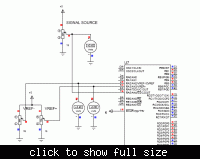
i'm using PIC 16F877A with 10bit ADC + i'm using highly stable Power supply along with capacitors + i'm using a 47uf capacitor on ADC channel & the Digital volt meter is reading a stable value, but i'm not able to get a stable ADC value why? what should i do now?

i am also doing Average of ADC value & the average window size is 10, still variations (+- 30) r there,

i'm using VRef- = 3.400 , VRef+ = 3.600 (as my analog device can provide signal in between this rang)

for the time being i'm using a 20K POT as my signal source.

if i connect my ADC channel to GND or VCC then it gives stabe value

in Proteus the results r perfect with no variations
 

hve yu ried o rea th daaheet to se wht mht ave gne wong? I uppose tose uys wo dsignd dvie knw soething aout ow t ue it corectly.

moderator

if you haven't anything useful to say that don't post anything.
 
Last edited by a moderator:

Hi,

With that set up you will never get a stable reading.

Your ADC window is just 0.2v which is then divided into 1023 steps, so each adc step is 0.000195v which explains your problems on the live circuit.

You should have an ADC window from 0 to 3.6v by just using Vref+.
 

Hi,

With that set up you will never get a stable reading.

Your ADC window is just 0.2v which is then divided into 1023 steps, so each adc step is 0.000195v which explains your problems on the live circuit.

You should have an ADC window from 0 to 3.6v by just using Vref+.

yeah when i don't use Vref+ & Vref- it gives perfect results but the problem is that my analog device output is from 3.45 to 3.55v
 

Strictly spoken, a setting of VRef- = 3.400 , VRef+ = 3.600 violates the datasheet specification A22 for VRef-, which effectively requires a minimum reference span of 2.0 V rather than 0.2V. But even if the datasheet won't explicitely specify a minimum span, it should be obvious that a too low span won't get you anywhere. You can simply assume, that most ADC error terms are effectively absolute voltage errors. So if you achieve e.g. 1 LSB accuracy with 5V Vref span, you can't expect more than 25 LSB with a span of 0.2 V, which is actually in the order of magnitude you observed. The only way to measure a limited voltage span without loosing accuracy is to use an external amplifier. Some PICs have also a PGA option for the ADC, which at least offers some improvement for reduced voltage ranges, altough it can't compete with an external amplifier.
 

Hi,

Would be helpful if you gave details of your analogue device .

If it outputs from 3.45 to 3.55 volts what resolution are you trying read into the PIC - just two decimal places or something much finer ?
 

i am surjeet
first u will have to use a resistance with input analog volt after that u have to add a capacitor ,
i sure,i will solve your problum
 

Status
Not open for further replies.

Similar threads

Part and Inventory Search

Welcome to EDABoard.com

Sponsor

Back
Top