Continue to Site

Welcome to EDAboard.com

Welcome to our site! EDAboard.com is an international Electronics Discussion Forum focused on EDA software, circuits, schematics, books, theory, papers, asic, pld, 8051, DSP, Network, RF, Analog Design, PCB, Service Manuals... and a whole lot more! To participate you need to register. Registration is free. Click here to register now.

PK2 LITE-blueroom electronics

Status
Not open for further replies.

pete g

Member level 1
Joined
May 18, 2009
Messages
35
Helped
1
Reputation
2
Reaction score
1
Trophy points
1,288
Activity points
1,538
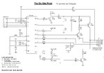
hi members, i want to build the above programmer. has anyone built it yet? looking over the schematic i'am confused about component D2(in5817). if its to be connected as shown, wouldn"t it be shorted out by the Vusb line?
 

Can you post the files? :)

---------- Post added at 15:34 ---------- Previous post was at 15:33 ----------

There are a lot if version also... so it is better to post one here :)
 

download.htm
: hi john, hope all is well. also what is the function of D2? thanks pg

---------- Post added at 19:37 ---------- Previous post was at 18:40 ----------

sorry, i tried to attach the url but was not successful. the web page is located at: dlmkerode.tripod.com/download.htm
 

Hi,

The Blueroom version of the Pickit2 "Lite" is well proven so no worries there.

D2 supplies the Targets +5v if the target is not powered.
Its important to use that type of diode as it only has a voltage drop of 0.2v.

The ferrite bead shown can be used if to hand but is not really needed.
The 680uh choke may be hard to find, I have used 470uf without any problems.

If you want to program 3v3 devices you can do it one of two was, either power the 3v3 target chip with 3v3 before conecting the Pk2, or insert a 3v3 regulator on the input +5v rail to the PK2 - both ways worked for me.


Search this forum for the many similar projects /designs some with ready designed pcb.

Don't forget you do need to first program the 18F2550 to get the PK2 working
 
  • Like
Reactions: pete g

    pete g

    Points: 2
    Helpful Answer Positive Rating
hi wp100, thanks for your response. according to the schematic, your suppose to connect the anode of the diode to 5v. is that the 5v supplied by the usb port? if so, it would appear that the diode would be shorted by the usb 5v line. regards pg.
 

Hi,

The Blueroom version of the Pickit2 "Lite" is well proven so no worries there.

D2 supplies the Targets +5v if the target is not powered.
Its important to use that type of diode as it only has a voltage drop of 0.2v.

Yup. The 5V will be supplied by the USB line.

it would appear that the diode would be shorted by the usb 5v line?
There is a resistor R10 there..... it won't short :)
 
  • Like
Reactions: pete g

    pete g

    Points: 2
    Helpful Answer Positive Rating
The IN5817 is in forward bias to the target which supplies 5volts through the USB. The diode isn't grounded in any way to complete the circcuit to say a "short" . As the Pickit 2 software has an monitoring option, the voltage at the Vcc pin (After the diode) is monitored by the Firmware PIC at pin 3 by the protection resistor R10. I coudnt see any "short" in the schematic. If your doubt isn't cleared yet, please upload the schematic (PDF or JPG) by marking the place where you find a short. Cheers
 
  • Like
Reactions: pete g

    pete g

    Points: 2
    Helpful Answer Positive Rating
hi,

Attached are Bluerrooms diagram and my own which may be a bit clearer regarding the USB +5v line.
 

Attachments

  • minipk2.jpg
    minipk2.jpg
    66.5 KB · Views: 155
  • pickit2_Lite.pdf
    44.6 KB · Views: 153
  • Like
Reactions: pete g

    pete g

    Points: 2
    Helpful Answer Positive Rating
hi guys, the PICKIT2 LITE that i built is the one featured on this web site: dlmkerode.tripod.com------i made the pc board that is featured, i think the layout is different, it appears they didn't use D2. i studied the layout of the pc board and can't find a place for D2. it appears that if you hook up D2 according to the schematic and read across it, you read a dead short? to say i'am confused, is an understatement. regards pg.
 

Hi,

it appears that if you hook up D2 according to the schematic and read across it, you read a dead short? to say i'am confused, is an understatement.

If you look at the blueroom schematic, D2s Anode is fed from the main USB +5v.
The Cathode goes out to the connector Pin2 which is the Vdd +5v to the chip to be programmed. ( as shown clearer on my diagram)

The function of D2 is that it allows you to program the Target chip when that chip is 'in circuit' and has its own power switched on. That power flows back up to the connector Pin 2 and would then try and feed back into the USB +5v, D2 prevents this.

(The fact that the USB +5v and the Targets +5v meet does not create a Short as such, the higher of the 2 voltages prevails.)

So, as long as you do not program ' in ciruit' with power on you do not need D2, though I would strongly suggest you do fit it now as I am sure you will want to do that in the future, though you may not think so now.

Edit - you might want to buy one of these Zif socket boards to match your Pk2 Lite - fanstastic value / quality - bought one myself
**broken link removed**
 
Last edited:
  • Like
Reactions: pete g

    pete g

    Points: 2
    Helpful Answer Positive Rating
hi wp100, voila! i have seen the light. thanks so much for your patience and help. regards pg.
 

can u please upload the values of the resistors again....not visible properly..thanks
 

can u please upload the values of the resistors again....not visible properly..thanks

The Mini Pk2 diagram is a bit hard to see, but the Pickit2Lite seems ok - the resistor values are the same in both , just they specify different transistor and diode numbers - though they are really the same types. The ferrite in the PK2Lite is not needed.
 

Status
Not open for further replies.

Part and Inventory Search

Welcome to EDABoard.com

Sponsor

Back
Top