Continue to Site

Welcome to EDAboard.com

Welcome to our site! EDAboard.com is an international Electronics Discussion Forum focused on EDA software, circuits, schematics, books, theory, papers, asic, pld, 8051, DSP, Network, RF, Analog Design, PCB, Service Manuals... and a whole lot more! To participate you need to register. Registration is free. Click here to register now.

[SOLVED] PIC18F2550 RB5 pin not functioning

Status
Not open for further replies.

denujith

Member level 5
Joined
Oct 5, 2010
Messages
85
Helped
6
Reputation
12
Reaction score
6
Trophy points
1,288
Activity points
1,886
Hi Everybody,

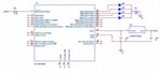
I have connected 4 LEDs to RB7, RB6, RB5 and RB4 pins of PIC18F2550 via a 470 ohm resistor. My intension is to blink LED one after the other.

My C code is:
Code:
#include <pic18.h>
#include <18f2550.h>

#pragma config FOSC = INTOSCIO_EC
#pragma config WDT = OFF

void delay (unsigned int interval){
	unsigned int i;
	for ( i=0; i!=interval; i++ );
}

void main(){
	char dir;
	TRISB = 0;
	PORTB = 0;
	while(1)
	{
		RB4 = 0;
		RB7 = 1;
		delay(2000);
		RB7 = 0;
		RB6 = 1;
		delay(2000);
		RB6 = 0;
		RB5 = 1;
		delay(2000);
		RB5 = 0;
		RB4 = 1;
		delay(2000);
	}		
}

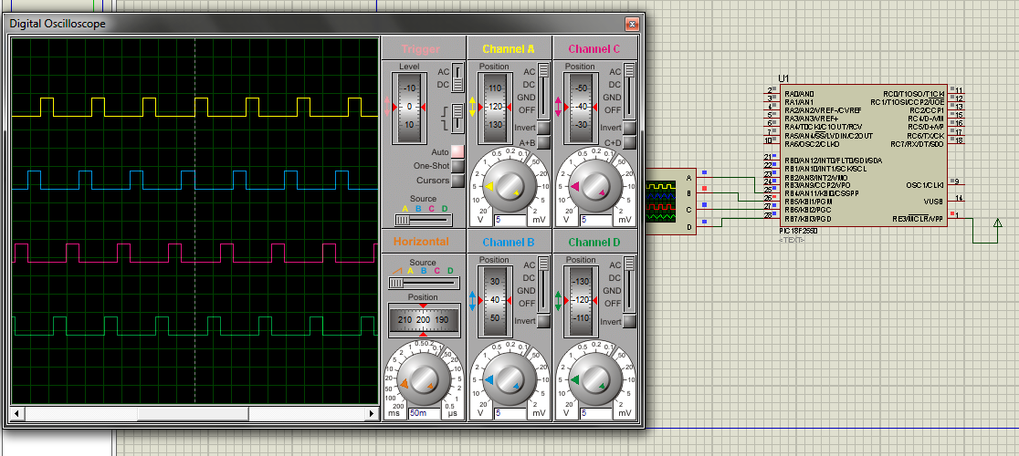
But LED connected to RB5 is not blinking. Can any one of you please let me know any reason as to why RB5 LED is not blinking?

Regards,
/Lakmal
 

Try using LATB,5 =1;

PORT registers read back the instantaneous pin state and the LAT registers read back what each pin was last written to. Look up "read/modify/write" to see why this matters
 

LATB5=1; didn't solve the problem. can you please explain more about "read/modify/write"?
 

do you disconnect your programmer when you run this? its the PGM pin sometimes its held high or low by programmers like PICKIT2
 

Yes I disconnected. Should I have to set CONFIG bits?
 

yes check the LVP bit, if it is set, all RB5's functions are disabled. Page 117 of the datasheet also page 312.
 
  • Like
Reactions: zlob2k

    zlob2k

    Points: 2
    Helpful Answer Positive Rating
These are my config bits:

Code:
#pragma config FOSC = INTOSCIO_EC
#pragma config WDT = OFF
#pragma config LVP = OFF
#pragma config BOR = ON
#pragma cinfig PWRT = ON

But, still it doesn't work
 

upload the hex file please.
 

It doesn't allow me to upload .hex files. says: Invalid File Type.
 

zip it, or change extension
 

I uploaded .hex as .zip
 

Attachments

  • MotorControler.zip
    379 bytes · Views: 108

This is the source file.
 

Attachments

  • main.zip
    427 bytes · Views: 95

the hex is perfectly alright, here is the simulation:


double check your hardware, last guess is the Port pin is faulty. Try another PIC.
 
Thank you a lot for your effort. I'll replace the PIC and try again.
 

This is my hardware setup. Just to make sure everything else is OK. :)
 

Attachments

  • led.jpg
    led.jpg
    49.7 KB · Views: 166

just a thought: using a common resistor for all the LED's is a bad practice, each one must have its own resistor to limit current. in your case only one LED lights at a time so its fine.
 

Hi spiralbrain,

I seems I have to replace PIC. :(
Anyway, Thank you a lot for your time and effort spent helping me.

/Lakmal
 

I remember you must do something to the LAT rather that the port directly. If not if will not work.

Can you try this and see whether it works:

LATB.5 = 1;
 

Cannot use LATB.5 = 1; Compile errors. I am planning to test on a new PIC. Thank you all for your help.
 

Status
Not open for further replies.

Similar threads

Part and Inventory Search

Welcome to EDABoard.com

Sponsor

Back
Top