Continue to Site

Welcome to EDAboard.com

Welcome to our site! EDAboard.com is an international Electronics Discussion Forum focused on EDA software, circuits, schematics, books, theory, papers, asic, pld, 8051, DSP, Network, RF, Analog Design, PCB, Service Manuals... and a whole lot more! To participate you need to register. Registration is free. Click here to register now.

[SOLVED] Wrong operating point of BANDGAP Reference

Status
Not open for further replies.

palmeiras

Full Member level 6
Joined
Feb 22, 2010
Messages
375
Helped
61
Reputation
122
Reaction score
50
Trophy points
1,308
Location
South America
Activity points
4,199
Hi Everybody,

Please, can anyone help me on this issue?

I have designed a traditional Bandgap voltage circuit, shown in figure 1 (VDD = 1.8V). It works properly. However, when I´m doing a DC simulations (Temperature sweep) in cadence, in some cases (for instance, in some corners), it stabilizes at a wrong operating point.

The wrong operating point is: Current IPTAT ~ pA and node_P = high values. The correct operating point is I1 ~ 20 uA and node_P = 1.2 V.
I have tried a start-up circuit, but it doesn’t work well for all cases. It still continues stabilizing at wrong op-point. I do believe that the problem is the start-up circuit. Am I right?

Do you have any suggestion of start-up circuit for this Bandgap topology?
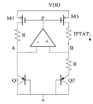

65_1285770435.jpg


Thank you very much,
 
Last edited:

you need start-up circuit for bandgap. but i think in terms of simulation, you can get the right operation point even without start-up.
anyway, what's the size of Q1 and Q2, respectively?
 

Thanks prcken,

Yes.. It is true. I have designed this circuit before, and the simulations run without start-up. But at this time, it seems to require this auxiliary circuit.
The size of bjt is around 80 um^2. Is this size relevant?
Do you have a example of start-up circut?
 

The size -ratio- affects ease of startup. Especially if the op amp
gain is low. And if you have more gain, you can run less startup
bias and have it less likely to "bend" operation once booted.
 
Q1 and Q2 have the same size? Q2 should be larger than Q1 or you may have a problem with the operating point.
 
Hi Guys,

Thanks for your help. The aspect ratio between both devices (Q1 and Q2) are 8. But the impact of the aspect ratio on the operating point is not clear for me yet.
A aspect ratio equal to 8 or 24, for instance. Which situation is better?
****_freebird, please, could you explain what you mean with "have it less likely to bend operation"?
 

The trick with startup circuits is, you have to get the
boot current high enough that the loop gain is useful.
Which means pushing something near Vbe onto the
diodes. But when they're up, you need to be pushing
no side current or you'll bend the ptat profile to some
other one, likely less ideal. The startup needs to cut
out above a minimum boot-current and below the min
operating current when the loop closes.

The more resilient your main loop is (ratio gain and op
amp gain; the latter can be very variable, and offsets
need to be accommodated) the more room between
min boot Vbe and operating Vbe, in which to steer the
boot current in/out.
 
Hi Guys,

Q2 is 8 times bigger than Q1.
Please, could you suggest a start-up circuit that you know it works?

Thanks so much,
 

i think there are more than one methods to do start-up and you could find it in the related text-books.
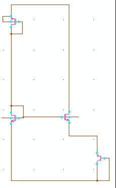
anyway, you can use this kind of start-up (i omitted the bandgap you showed with only Q1 left in the schematic)
80_1285945691.jpg
 
Thanks prcken, I will simulate it and soon, I will come back with the results.
 

Status
Not open for further replies.

Part and Inventory Search

Welcome to EDABoard.com

Sponsor

Back
Top