amangupta009
Newbie level 3
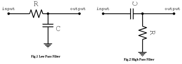
Q1. How capaitor acts as a filter ?(reason behind its action)
Q2. Why capacitors with high capacitance are used at power rails and the one with low capacitance at power dips ?? ( i am asking how to decide which capacitor should be used where )
Q3. Why capacitor blocks dc current while allows ac current to pass? i know mathematically but want to know physically
")