Continue to Site

Welcome to EDAboard.com

Welcome to our site! EDAboard.com is an international Electronics Discussion Forum focused on EDA software, circuits, schematics, books, theory, papers, asic, pld, 8051, DSP, Network, RF, Analog Design, PCB, Service Manuals... and a whole lot more! To participate you need to register. Registration is free. Click here to register now.

load/pull analysis in cadence using harmonic balance simualtion

Status
Not open for further replies.

zopeon

Member level 2
Joined
Sep 12, 2008
Messages
51
Helped
7
Reputation
14
Reaction score
2
Trophy points
1,288
Location
India
Activity points
1,612
Hi,
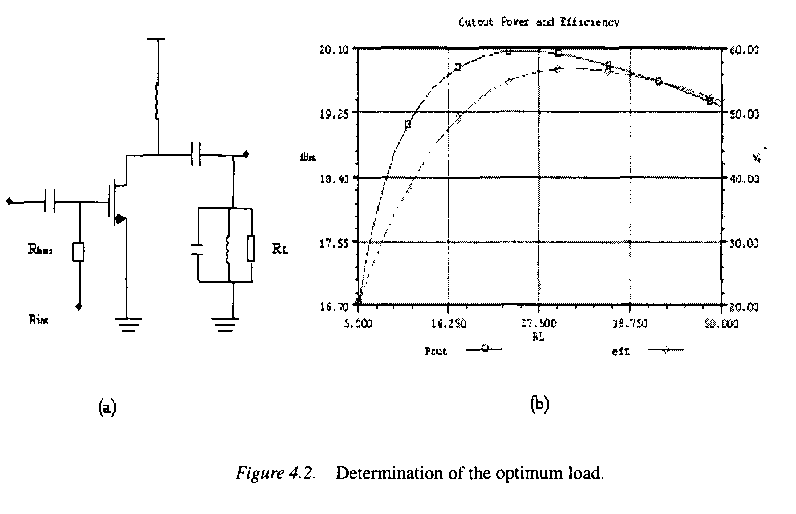
I am new to power amplifier design. I had referred RF power amplifier design by Hella & Ismail. They had said to select MOSFET sizing based on efficiency( assumed) and bias condition as a starting point and then run harmonic balance analysis to find the optimum load for the chosen size. I have attached the circuit diag. I have set the input port impedance to conjugate match the MOSFET input ( 200 + 800i) and set the variable RL as output port. Can someone tell me how to set the cadence harmonic analysis, I tried to do it and plot power contour but it displayed two dimensional sweep required.


Thanks
 

Ouput isn't conjugated matched to the output of the power amlifiers.Instead Load-Pull technique is used to find the optimum load impedance which is seen by the amplifier itself.
In cadence Design Environment, you can simulate your circuit by changing real and imaginary part of your load impedance on the Smith Chart and at each point you note the Delivered Power.In order to change your load, you should use "Gamma" components in rf_lib ( as I remember ) that has variable real part and imaginary part.You can define these normalized variables by serially changing strings like ..
[0.5,0.1],[0.5,-0.1],[0.5,0.2],[0.5,-0.2]...etc..First define coarse points and then get them shrink in a narrow region.

In ADS, it's quite simple to do this..
There is a Load Pull Templates and by using this template, you may find optimum impedance.
All you should do is to replace the sample amplifier by yours.Of course don't forget to cahange Vdd and other biasing conditions and the operating frequency.
In advanced level, the optimum source impedance should be defined and harmonic impedances are also optimized..etc.
 

Thanks for the reply,
Could you tell me which analysis to do in cadence to get the power contours? my goal is to find the optimum power for the chosen MOSFET width. I am only simulating the power amplifier with its input conjugate matched and output connected to port(variable impedance) and how to get power contours I am getting them as flat lines along the axis on smith chart.
 

Status
Not open for further replies.

Part and Inventory Search

Welcome to EDABoard.com

Sponsor

Back
Top