Continue to Site

Welcome to EDAboard.com

Welcome to our site! EDAboard.com is an international Electronics Discussion Forum focused on EDA software, circuits, schematics, books, theory, papers, asic, pld, 8051, DSP, Network, RF, Analog Design, PCB, Service Manuals... and a whole lot more! To participate you need to register. Registration is free. Click here to register now.

[SOLVED] load in series with SCR(thysistor)

Status
Not open for further replies.

mystic07

Junior Member level 2
Joined
Aug 22, 2010
Messages
20
Helped
5
Reputation
10
Reaction score
5
Trophy points
1,283
Location
mauritius
Activity points
1,411
load in series with SCR(thyristor)

Why should a load always be connected to the anode side of the SCR???
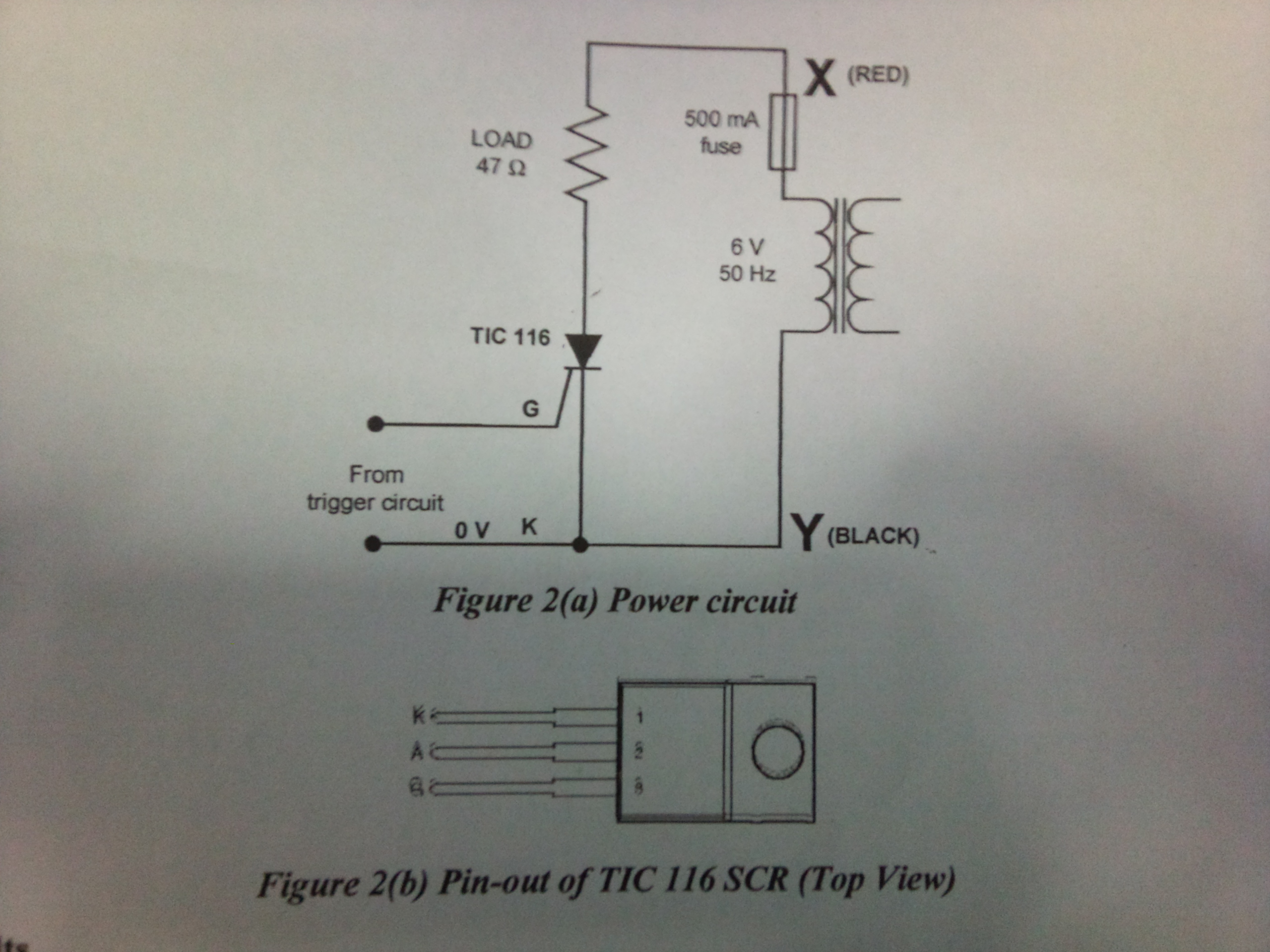
the diagram is as follows:


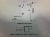
the voltage across the load was measured with a CRO.

what would happen if the load's position was exchanged with that of th SCR?

i,ve search the web but cannot find the answer. could anyone please help? thanks

(any relevant link would be really helpful, if possible)
 
Last edited:

It would work exactly the same - BUT, the voltage to turn the SCR on still has to be applied between the gate and cathode pins so the driving circuit would have to be able to handle the full load voltage instead of just a few volts.

Brian.
 
It would work exactly the same - BUT, the voltage to turn the SCR on still has to be applied between the gate and cathode pins so the driving circuit would have to be able to handle the full load voltage instead of just a few volts.

Brian.

yeah that's what i thought too. but when i asked my teacher said that there will be a short circuit through the CRO or something like that. i didn't quite understand. and he said that to overcome this problem, an IGBT should be used instead of an SCR. snif!!! i really can't understand :((
 

Your teacher is wrong!
They are assuming something that is not in the schematic, that the 0V rail is also ground to the CRO. What I think they are warning of is that if you connected a CRO (Oscilloscope) across the SCR, and one side of the oscilloscope was grounded through it's power cable, the voltage might be shorted out along the oscilloscope probe cable, through the oscilloscope circuits and back through the mains cable and power supply to your circuit. None of that is made clear in the circuit you show. I understand their concerns but technically, as long as the trigger voltage is placed across the gate and cathode, and there is sufficient voltage between anode and cathode, the SCR will conduct.
It is common practice to use SCRs in circuits where the the cathode is the load side, in fact I've just done it in a pump control unit and I confirm it works perfectly.
Brian.
 
he said that to overcome this problem, an IGBT should be used instead of an SCR
The suggestion doesn't seem to solve a problem (if any exist) but creates new instead. Unlike a SCR, a basic iGBT has no reverse blocking capabiliities, it can be even damaged by applying a reverse voltage. The basic difference is it's turn-off capability, but I don't see that it's related to the discussed problem.

if the load's position was exchanged with that of th SCR
It hasn't been explicitely said, if the trigger circuit's common terminal should be still connected to the SCR cathode. I expect, it would, as betwixt did. In this case, there's no problem, because the input voltage is isolated by the transformer. It's also not been said, if the "0V" node is connected to protective earth or if it's floating.
 
Yes the 0V was indeed connected to the ground(earth). thanks....:D
 

Status
Not open for further replies.

Part and Inventory Search

Welcome to EDABoard.com

Sponsor

Back
Top